Amplifer Noise Analysis
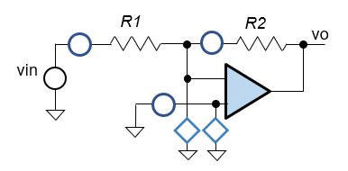
Inverting Amplfier
A key aspect of precision amplifier design must answer this question - how will noise impact the accuracy? While many application notes show the complex equations, few break them down or create an analysis tool for your own designs. This topic provides
- a step-by-step approach
- walk thru each error source
- derive the circuit and sensitivity equations
- an Excel file
- enter errors in a systematic format
- vary parameters, see their effect on total error
- customize & expand template for your own designs
To verify the method, we'll calculate the noise as found in "Noise Calculations of Op-Amp Circuits", Example 1, Application Note by Renesas.
For tutorials and other examples, goto EBA Series
OFFSET AND GAIN ERRORS
We'll start with basic error definitions of an amplifier block. What are Offset and Gain Errors?
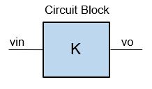
- Ideal Amplifier with Gain K
- Vo = Vin*K
- Actual Amplifier with errors
- Vo = Vin* (K+∆K) + ∆Voffset
- ∆K - Gain Error
- change in Gain from ideal (K).
- also called Slope, Span error
- ∆Voffset - Offset Error
- change in offset from ideal (0V)
- also called Intercept, Zero Error
- Combined Offset and Gain Errors
- Error = ±∆Voffset + ( ±∆K x Reading )
QUESTION: Is noise an Offset or Gain Error? Because noise does not
scale with the input signal, it's classified as an Offset Error.
Further, noise is uncalibratable, so it falls under the "Noise, Drift, etc."
category.
MAX ERROR BUDGET
The max budget (target spec) for the amplifier has been chosen as:
- Offset Error: ∆Voffset = 100 uV
- Gain Error: ∆K/K = 0.5% of Reading
AMPLIFIER NOISE
Schematic with Errors
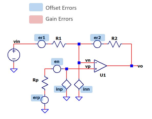
Device Errors
We'll analyze noise errors only for this topic. (For DC Errors check out Amp1 Error Analysis.)
| Description | Error |
|---|---|
| NOISE ERRORS | |
| U1, Input Voltage Noise, en (white and 1/f noise) U1, Input Current Noise, inp (white and 1/f noise) U1, Input Current Noise, inn (white and 1/f noise) Rp, Resistor Noise, er R1, Resistor Noise, er R2. Resistor Noise, er |
15 (nV/√Hz), 82 nV*√1Hz 0.35 (nA/√Hz), 8 nA*√1Hz 0.35 (nA/√Hz), 8 nA*√1Hz 1,000 1,010 101,000 |
Conditions and Assumptions
Temperature
- Ambient: Ta = 25C
Amplifier
- Rp = 1000, R1=1010, R2=101000
- K = -R2/R1 = -100
- fbw = 49.5 kHz (single-pole low-pass response)
- fL = 0.1Hz (lower freq for 1/f noise calc)
Errors
- The Op Amp's White and 1/f Noise are calculated separately.
- Noise errors are calculated at vo first, then Referred to Input (RTI) at Vin.
- Errors totaled as RSS (Root Sum Squared)
RESISTOR NOISE (THEORY REFRESH)
NOISE DENSITY
Resistors create a voltage noise density per root Hz given by
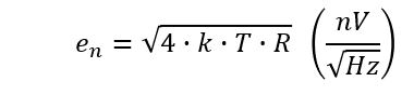
where
k = 1.38e−23 J/K is Boltzmann's constant
T = absolute temperature in kelvins (298K at 25C)
R = resistance in ohms.
RMS NOISE
The total RMS noise in a given bandwidth can be predicted by
where
fbw - cutoff frequency of the bandwidth
Kbw - equivalent noise bandwidth multiplier
(Kbw =
1.57 for a single pole Low-Pass response)
PEAK NOISE
The peak noise becomes![]()
The multiplier 3 expands the rms coverage of 1σ (68.7% of
samples) to 3σ (99.7% of samples).
RESISTOR NOISE (Rp)
NOISE DENSITY, RMS, PEAK
Check out the equations already covered in
"Resistor Noise (Theory Refresh)" above.
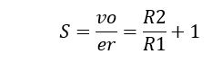
SENSITIVITY
How does the resistor noise source impact vo? Because er appears at
U1's positive input, the non-inverting gain applies.
Let's run through the noise calculations.
| Description | Noise |
| Error Source: e e = √(4*k*T*R) |
R = 1000 ohms Convert to noise density: er = √( 4*1.38e-23*298*1000) = 4.1 nV/√Hz |
| Pick Analysis Node: Va | vo |
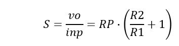
| Calc Sensitivity: S How does e impact Va? |
S =
vo/er = R2/R1+1 = 101k/1.01k+1 = +101 |
| Calc peak Noise Error at Analysis Node ∆Voffset = e * √(fbw*Kbw) * 3 * S |
∆Voffset = er*√(fbw*Kbw)*3*S = 4.1 nV*√(49kHz*1.57)*3*101 = 344 uVpk |
| Calc Gain from Input to Analysis Node: Ka = Va / Vin |
Ka = vo/vin = -R2/R1 = -100 |
| Calc Error RTI (Referred-to-Input): ∆voffset_RTI = ∆voffset / Ka |
∆voffset_RTI = 344 uVpk / -100 = -3.4 uVpk (1.1 uVrms) |
RESISTOR NOISE (R1)
NOISE DENSITY, RMS, PEAK
Check out the equations already covered in
"Resistor Noise (Theory Refresh)" above.
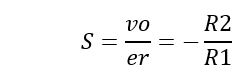
SENSITIVITY
How does R1 noise source impact vo? Because er appears
in the series with R1, the inverting gain applies.
Let's run through the noise calculations.
| Description | Noise |
| Error Source: e e = √(4*k*T*R) |
R = 1010 ohms Convert to noise density: er = √( 4*1.38e-23*298*1010) = 4.1 nV/√Hz |
| Pick Analysis Node: Va | vo |
| Calc Sensitivity: S How does e impact Va? |
S =
vo/er = -R2/R1 = 101k/1.01k = -100 |
| Calc peak Noise Error at Analysis Node ∆Voffset = e * √(fbw*Kbw) * 3 * S |
∆Voffset = er*√(fbw*Kbw)*3*S = 4.1 nV*√(49kHz*1.57)*3*(-100) = -341 uVpk |
| Calc Gain from Input to Analysis Node: Ka = Va / Vin |
Ka = vo/vin = -R2/R1 = -100 |
| Calc Error RTI (Referred-to-Input): ∆voffset_RTI = ∆voffset / Ka |
∆voffset_RTI = -343 uVpk / -100 = 3.4 uVpk (1.1 uVrms) |
RESISTOR NOISE (R2)
NOISE DENSITY, RMS, PEAK
The noise equations were already covered
above in "Resistor Noise (Theory
Refresh)".
SENSITIVITY
The gain from er of R2 to vo may not be
obvious. Because it appears
in the series with R2, the gain is unity.
![]()
Running through the calculations, we get
| Description | Noise |
| Error Source: e e = √(4*k*T*R) |
R = 101k ohms Convert to noise density: er = √( 4*1.38e-23*298*101k) = 41 nV/√Hz |
| Pick Analysis Node: Va | vo |
| Calc Sensitivity: S How does e impact Va? |
S =
vo/er = 1 |
| Calc peak Noise Error at Analysis Node ∆Voffset = e * √(fbw*Kbw) * 3 * S |
∆Voffset = er*√(fbw*Kbw)*3*S = 41 nV*√(49kHz*1.57)*3*1 = -34 uVpk |
| Calc Gain from Input to Analysis Node: Ka = Va / Vin |
Ka = vo/vin = -R2/R1 = -100 |
| Calc Error RTI (Referred-to-Input): ∆voffset_RTI = ∆voffset / Ka |
∆voffset_RTI = -34 uVpk / -100 = 0.34 uVpk (0.1 uVrms) |
OP AMP NOISE (THEORY REFRESH)
Two random behaviors make up the op amp input voltage noise: white noise (ew) and 1/f noise (ef). They sum together as Root Sum Square (RSS) for a total input noise (en).
WHITE NOISE DENSITY
Op amps create a fixed noise density (ew) in
volts per root Hz.
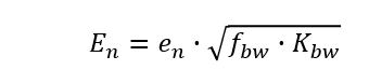
NOISE RMS
The total RMS of white noise can be predicted by
![]()
where
fbw - cutoff frequency of the bandwidth
Kbw - equivalent noise bandwidth multiplier
(Kbw =
1.57 for a single pole Low-Pass response)
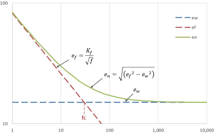
1/f NOISE DENSITY
Op amps also create a 1/f or flicker noise that
falls at a constant rate per square root of frequency
where
Kf is the constant fall rate for the device.
Kf is defined by the white noise and 1/f corner frequency.
![]()
However, it's easily approximated by reading the noise density (en) at
the lowest frequency (fx) on the 1/f plot.
![]()
NOISE RMS
The total RMS of flicker noise can be calculated by
where
fL, fH - lower and upper frequencies of analysis
Kf - the 1/f constant for the device
PEAK NOISE
The peak noise for an RMS level becomes![]()
The multiplier 3 expands the rms coverage of 1σ (68.7% of
samples) to 3σ (99.7% of samples).
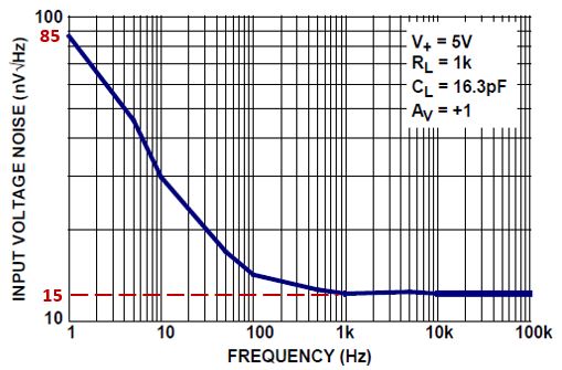
INPUT VOLTAGE NOISE (en)
NOISE PLOT
Read the noise levels from the plot (Op Amp ISL28136).
NOISE DENSITY, RMS, PEAK
Check out the equations already covered in
"Op Amp Noise (Theory Refresh)" above.
SENSITIVITY
How does the input noise source impact vo? Because en appears at
U1's positive input, the non-inverting gain applies.
Let's run through the noise calculations.
| Description | White Noise | 1/f Noise |
| Error Source: e | Read en from plot at highest frequency en = 15 nV/√Hz |
Read en at lowest frequency fx and calculate Kf = en(fx) * √fx = 85nV/√Hz * √(1 Hz) = 85nV |
| Pick Analysis Node: Va | vo | vo |
| Calc Sensitivity: S How does e impact Va? |
S =
vo/er = R2/R1+1 = 101k/1.01k+1 = +101 |
S = 101 |
| Calc peak Noise Error at Analysis Node |
∆Voffset = en*√(fbw*Kbw)*3*S = 15 nV*√(49k*1.57)*3*101 = 1270 uVpk |
∆Voffset = Kf* √ln(fH/fL) *3*S = 85nV * √ln(49k/1)*3*101 = 93 uVpk |
| Calc Gain from Vin to Analysis Node: Ka = Va / Vin |
Ka = vo/vin = -R2/R1 = -100 |
Ka = -100 |
| Calc Error RTI (Referred-to-Input): ∆voffset_RTI = ∆voffset / Ka |
∆voffset_RTI = 1270 uVpk / -100 = -12.7 uVpk (4.2 uVrms) |
∆voffset_RTI = 93 uVpk / -100 = -0.93 uVpk (0.31 uVrms) |
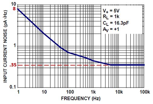
INPUT CURRENT NOISE (inp)
NOISE PLOT
Read the levels from the plot (Op Amp
ISL28136).
NOISE DENSITY, RMS, PEAK
Check out the equations already covered in
"Op Amp Noise (Theory Refresh)" above.
SENSITIVITY
How does the positive input current noise impact vo?
Current inp flows into RP creating a voltage that is then amplified by the
non-invering gain.
Running through the calculations, we get
| Description | White Noise | 1/f Noise |
| Error Source: e | Read in from plot at highest frequency inp = 0.35 nA/√Hz |
Read in at lowest frequency fx and calculate Kf = in(fx) * √fx = 8nA/√Hz * √(1 Hz) = 8nA |
| Pick Analysis Node: Va | vo | vo |
| Calc Sensitivity: S How does e impact Va? |
S =
vo/er = Rp*(R2/R1+1) = 1000*(101k/1.01k+1) = +101k |
S = 101k |
| Calc peak Noise Error at Analysis Node |
∆Voffset
=in*√(fbw*Kbw)*3*S =0.35nA*√(49k*1.57)*3*101k =30 uVpk |
∆Voffset = Kf* √ln(fH/fL) *3*S = 8nA*√ln(49k/0.1)*3*101k = 8.8 uVpk |
| Calc Gain from Vin to Analysis Node: Ka = Va / Vin |
Ka = vo/vin = -R2/R1 = -100 |
Ka = -100 |
| Calc Error RTI (Referred-to-Input): ∆voffset_RTI = ∆voffset / Ka |
∆voffset_RTI = 30 uVpk / -100 = -0.3 uVpk (0.1 uVrms) |
∆voffset_RTI = 8.8 uVpk / -100 = -0.09 uVpk (0.03 uVrms) |
INPUT CURRENT NOISE (inn)
NOISE PLOT
Read the levels from plot for current noise inp.
NOISE DENSITY, RMS, PEAK
Check out the equations already covered in
"Op Amp Noise (Theory Refresh)" above.
SENSITIVITY
The impact of inn is not so obvious.
Working through the equations you find the gain similar to a transimpedance
amplifier config.
![]()
Running through the calculations, we get
| Description | White Noise | 1/f Noise |
| Error Source: e | Read in from plot at highest frequency inp = 0.35 nA/√Hz |
Read in at lowest frequency fx and calculate Kf = in(fx) * √fx = 8nA/√Hz * √(1 Hz) = 8nA |
| Pick Analysis Node: Va | vo | vo |
| Calc Sensitivity: S How does e impact Va? |
S =
vo/er = -R2 = -101k |
S = -101k |
| Calc peak Noise Error at Analysis Node |
∆Voffset =in*√(fbw*Kbw)*3*S =0.35nA*√(49k*1.57)*3*101k =30 uVpk |
∆Voffset = Kf* √ln(fH/fL) *3*S = 8nA*√ln(49k/1)*3*101k = 8.8 uVpk |
| Calc Gain from Vin to Analysis Node: Ka = Va / Vin |
Ka = vo/vin = -R2/R1 = -100 |
Ka = -100 |
| Calc Error RTI (Referred-to-Input): ∆voffset_RTI = ∆voffset / Ka |
∆voffset_RTI = 30 uVpk / -100 = -0.3 uVpk (0.1 uVrms) |
∆voffset_RTI = 8.8 uVpk / -100 = -0.09 uVpk (0.03uVrms) |
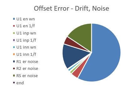
SUMMARY
Let's review the Noise Errors from the Offset Error sheet.
Description |uVpk| uVrms NOISE ERRORS U1 en (white noise)
(1/f noise)
U1 inp (white noise)
(1/f noise)
U1 inn (white noise)
(1/f noise)12.7
0.9
0.3
0.1
0.3
0.14.22
0.31
0.10
0.03
0.10
0.03Rp er (thermal noise)
R1 er (thermal noise)
R2 er (thermal noise)3.4
3.4
0.31.14
1.14
0.11
Total noise must be calculated using Root Sum Squares (RSS).
- RSS = √(∆Voffset12 + ∆Voffset22 + ...)
= 13.6 uVpk (4.53 uVrms)
Does the Total Noise Error (peak) fly under the Max Error Budget?
- RSS < 100 uVpk Yes - PASS!
NOISE VS. APP NOTE?
- The noise calculations were very similar to results in the App note!
- The App Note had a 1% lower noise. Why? It appears the App Note calculated the noise at the op amp's input, but omitted the final step of referring the noise to Vin. This omission under-estimates noise for inverting amplifiers. The impact is more noticable for lower gains.
- This method explicitly calculates noise at Vin.
EBA WITH EXCEL
An Excel file was created to implement the error budget analysis.
- Organizes complex analyses into smaller managable sections
- Easier to create, review and debug
- Customizable and expandable to more complex circuits
- Modular for reuse in other designs
3 Worksheets
Worksheet Enter Calculate CIRCUIT CALC Circuit values Signal gains, levels and error sensitivities (S) OFFSET Offset error sources Offset errors and totals GAIN Gain error sources Gain errors and totals
While 3 worksheets seems over-the-top for smaller circuits,
you'll find a big advantage when analyzing more complex circuits or
multi-stage systems!
Try the Excel file: amp1-noise.xlsx
Right Click on the filename, select "Save link as...".
- Open file, explore the Calc, Offset and Gain Sheets
- Hover over RED cornered cells for special noise calc notes!
- Play in the sandbox, modify values, see the impact on errors.
- Copy to a new file - experiment!
TRY IT!
- Increase all resistors by 10x (for a lower power design).
- What effect does this have on total noise?
- Suppose you're asked to try an op amp with 5x the input voltage noise (for a lower cost design).
- Does the amplfier design still meet spec?
REFERENCES
- Noise Calculations of Op-Amp Circuits, Application Note, Renesas Electronics.
- ISL28136, Precision, Rail-to-Rail, Op Amp Datasheet, Renesas Electronics.
- Tolerance Design of Electronic Circuits, Robert Spence, Randeep Soin, World Scientific Publishing.
For in-depth tutorials and more circuits, go to
EBA Series