Basic Amplifier
Non-Inverting Op Amp
A basic op amp config provides a great intro to Error Budget Analysis! We'll do a teardown of this critical and challenging analysis. You'll get
- a step-by-step approach
- walk thru each error source
- derive the circuit and sensitivity equations
- an Excel file
- enter errors in a systematic format
- vary parameters, see their effect on total error
- customize & expand for your own designs
For tutorials on Key Concepts and other circuits, goto EBA Series
For the same magnitiude of gain, which has the larger errors, the Non-Inverting (K = +5) versus the Inverting (K = -5) config?
OFFSET AND GAIN ERRORS
We'll start with basic error definitions of an amplifier block. What are Offset and Gain Errors?
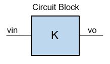
- Ideal Amplifier with Gain K
- Vo = Vin*K
- Actual Amplifier with errors
- Vo = Vin* (K+∆K) + ∆Voffset
- ∆K - Gain Error
- change in Gain from ideal (K).
- also called Slope, Span error
- ∆Voffset - Offset Error
- change in offset from ideal (0V)
- also called Intercept, Zero Error
- Combined Offset and Gain Errors
- Error = ±∆Voffset + ( ±∆K x Reading )
MAX ERROR BUDGET
The max budget (target spec) for amplifier has been chosen as:
- Offset Error: ∆Voffset = 5mV
- Gain Error: ∆K = 1% of Reading
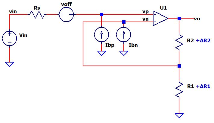
AMPLIFIER
Schematic with Error Sources
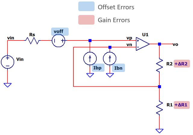
Error Sources
Description Initial Drift OFFSET ERRORS voff, Input Offset Voltage
ibn, Input Bias Current (Pos)
ibp, Input Bias Current (Neg)1 mV
10 nA
10 nA10 uV / C
1 nA / C
1 nA / CGAIN ERRORS R2_Tol
R1_Tol0.1 %
0.1 %100 ppm / C
100 ppm / C
Conditions and Assumptions
Temperature
- Ambient: Ta = 25C
- Max change: ∆T = 30C
Amplifier
- Rs = 500, R1=10k, R2=40k
- K = R2/R1+1 = +5.0
- Vin = 1V, Vo = 5V
Errors
- All errors can be either polarity +/-.
- Errors will be Referred to Input (RTI)
- Errors totalled as Worst Case (sum absolute values)
OFFSET ERRORS
The Non-Inverting Amplfier nicely showcases the EBA method. You can modify the analysis for the Inverting or other Op Amp configurations.
While the steps may seem more detailed than needed for simpler errors,
the value of creating a systematic approach will pay off when
analyzing more complex, multi-stage designs.
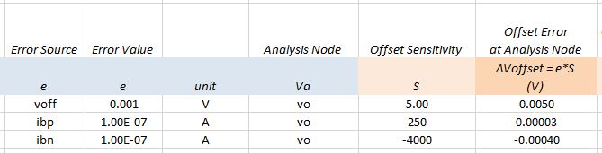
INPUT OFFSET VOLTAGE
Because voff is modelled as voltage in series with the pos input, it gets amplified just like the signal gain for Vin.
| Description | Initial Errors | Drift Errors |
| Error Source: e | voff = 1mV | voff_TC = 10uV/C |
| Pick Analysis Node: Va | vo | vo |
| Calc Sensitivity: S How does e impact Va? |
S = vo / voff = R2/R1+1 = 5 |
S = 5 |
| Calc Offset Error at Analysis Node Initial: ∆Voffset = e * S Drift: ∆Voffset = e * ∆T * S |
∆Voffset = 1mV * 5 = 5mV |
∆Voffset = 10uV/C * 30C * 5 = 1.5 mV |
| Calc Gain from Input to Analysis Node: Ka = Va / Vin |
Ka = vin/vo = R2/R1+1 = 5 |
Ka = 5 |
| Calc Error RTI (Referred-to-Input): ∆voffset_RTI = ∆voffset / Ka |
∆voffset_RTI = 5mV / 5 = 1mV |
∆voffset_RTI = 1.5mV / 5 = 0.3mV |
INPUT BIAS CURRENT (NEG)
To make the initial learning of error analysis easier, the input bias currents were treated as simple independent sources. (For a more complex model, see Advanced Amplifier).
The op amp acts like a transimpedance amplifier converting the current ibn to a voltage vo = ibn*(-R2).
| Description | Initial Errors | Drift Errors |
| Error Source: e | ibn = 10nA | ibn_TC = 1nA/C |
| Pick Analysis Node: Va | vo | vo |
| Calc Sensitivity: S How does e impact Va? |
S = vo / ibn = -R2 = -40000 |
S = -40000 |
| Calc Offset Error at Analysis Node Initial: ∆Voffset = e * S Drift: ∆Voffset = e * ∆T * S |
∆Voffset = 10nA * -40000 = -0.4mV |
∆Voffset = 1nA/C * 30C * -40000 = -1.2mV |
| Calc Gain from Input to Analysis Node: Ka = Va / Vin |
Ka = vin/vo = R2/R1+1 = 5 |
Ka = 5 |
| Calc Error RTI (Referred-to-Input): ∆voffset_RTI = ∆voffset / Ka |
∆voffset_RTI = -0.400mV / 5 = -0.080mV |
∆voffset_RTI = -1.200mV / 5 = -0.240mV |
INPUT BIAS CURRENT (POS)
Easy to analyze - ibp flows into Rs creating a voltage, then gets amplified by the non-inverting signal gain.
| Description | Initial Errors | Drift Errors |
| Error Source: e | ibp = 10nA | ibp_TC = 1nA/C |
| Pick Analysis Node: Va | vo | vo |
| Calc Sensitivity: S How does e impact Va? |
S = vo / ibp = Rs*(R2/R1+1) = 500*5 = 2500 |
S = 2500 |
| Calc Offset Error at Analysis Node Initial: ∆Voffset = e * S Drift: ∆Voffset = e * ∆T * S |
∆Voffset = 10nA * 250 = 0.025mV |
∆Voffset = 1nA/C * 30C * 2500 = 0.075mV |
| Calc Gain from Input to Analysis Node: Ka = Va / Vin |
Ka = vin/vo = R2/R1+1 = 5 |
Ka = 5 |
| Calc Error RTI (Referred-to-Input): ∆voffset_RTI = ∆voffset / Ka |
∆voffset_RTI = 0.025mV / 5 = 0.005mV |
∆voffset_RTI = 0.075mV / 5 = 0.015mV |
GAIN ERRORS
Gain errors often require more effort when calculating the Sensitivity S.
RESISTOR R2
To find the Sensitivity of K to R2, you can apply the Difference Method. Simply increment R2 by an arbitrarily small ratio (say 0.01) and calculate its impact on K.
| Description | Initial Errors | Drift Errors |
| Error Source: e | R2_Tol = 0.1% |
R1_TC = 100ppm/C = 0.0001%/C |
| Pick Analysis Node: Va | vo | vo |
| Calc Sensitivity: S How does e impact Gain K? Apply Difference Method: S = (∆K/K) / (∆R/R) where ∆K/K = (K'-K)/K |
K = R2/R1+1 R2 = 40k R1 =10k K = 40k/10k+1 = 5.0 K'=40k*1.01/10k+1 = 5.04 ∆R/R = 0.01 S = (∆K/K) / (∆R/R) = +0.8 |
S = 0.8 |
| Calc Gain Error at Analysis Node Initial: ∆K/K = e * S Drift: ∆K/K = e * ∆T * S |
∆K/K = 0.1% * 0.8 = 0.08% |
∆K/K = 100ppm/C*30C*0.8 = 2400ppm = 0.24% |
| Normailzed gain errors can be referred to input as-is, no RTI calc needed. |
RESISTOR R1
To find the Sensitivity of K to R1, you can apply the Difference Method. Simply increment R1 by an arbitrarily small ratio (say 0.01) and calculate its impact on K.
| Description | Initial Errors | Drift Errors |
| Error Source: e | R1_Tol = 0.1% |
R1_TC = 100ppm/C = 0.0001%/C |
| Pick Analysis Node: Va | vo | vo |
| Calc Sensitivity: S How does e impact Gain K? Apply Difference Method: S = (∆K/K) / (∆R/R) where ∆K/K = (K'-K)/K |
K = R2/R1+1 R2 = 40k R1 =10k K = 40k/10k+1 = 10.0 K'=40k/(10k*1.01)+1 = 4.96 ∆R/R = 0.01 S = (∆K/K) / (∆R/R) = -0.8 |
S = -0.8 |
| Calc Gain Error at Analysis Node Initial: ∆K/K = e * S Drift: ∆K/K = e * ∆T * S |
∆K/K = 0.1%*-0.8 = -0.08% |
∆K/K = 100ppm/C*30C*-0.8 = -2400ppm = -0.24% |
| Normalized gain errors can be referred to input as-is, no RTI calc needed. |
SUMMARY
Let's review the Gain & Offset errors.
Description Initial (V) Drift (V) OFFSET ERRORS voff, Input Offset Voltage
ibp, Input Bias Current (Pos)
ibn, Input Bias Current (Neg)1.000 mV
0.005 mV
-0.080 mV0.300 mV
0.015 mV
-0.240 mVGAIN ERRORS R2_Tol
R1_Tol0.08 %
-0.08 %0.24 %
-0.24 %
TOTAL OFFSET ERROR
Calculate the total using Worst Case Analysis. WCA assumes the most unfavorable conditions: all errors at their maximum limit AND in the same polarity.
- WCA = | ∆Voffset1 | + | ∆Voffset2 | + ...
= 1.6mV
Does the Total Error fly under the Max Error Budget (Requirements)?
- WCA < 5.0mV?
Yes - PASS!
TOTAL GAIN ERROR
Calculate the total using Worst Case Analysis.
- WCA = | ∆K1 | + | ∆K2 | + ...
= 0.64 %
Does the Total Error fly under the Max Error Budget (Requirements)?
- WCA < 1.0%?
Yes - PASS!
EBA WITH EXCEL
An Excel file was created to implement the error budget analysis.
- Organizes complex analyses into smaller managable sections
- Easier to create, review and debug
- Customizable and expandable to more complex circuits
- Modular for reuse in other designs
3 Worksheets
Worksheet Enter Calculate CIRCUIT CALC Circuit values Signal gains, levels and error Sensitivities OFFSET Offset error sources Offset errors and totals GAIN Gain error Sources Gain errors and totals
While 3 worksheets seems over-the-top for smaller circuits, you'll find a big advantage when analyzing more complex circuits or multi-stage systems!
Try the hands-on spreadsheet!
- Excel file: amp1-basic-b.xlsx
Right Click on the filename, select "Save link as...". - Open file, explore the Calc, Offset and Gain Sheets
- Play in the sandbox, modify values, see the impact on errors.
- Copy to a new file - experiment!
NOTES, IDEAS...
- For in-depth tutorials, go to EBA series.
- Try the Inverting Amp. Copy to new file and modify Circuit Calc sheet.
- Add another stage. Copy Circuit Calc to a new sheet and modify for new stage. Add new rows to existing Offst / Gain Error sheets.
Back to EBA Series