Measure DC Volts
CIRCUIT

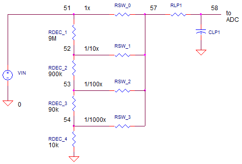
DMM_VDC_MEAS1.CIR Download the SPICE file
The core of a Digital Multi-Meter (DMM) can do one thing very well - convert an analog voltage to a digital representation. Typically, this Analog-to-Digital Converter (ADC) has been designed and optimized for a single voltage range, +/-2V for example. So how does the DMM not only measure other voltage ranges ( 2000V, 200V, 20V ), but also other parameters as well such as current, resistance or capacitance? The DMM presents a design challenge of converting all other measurements into a 2V Full Scale voltage measurement!
THE DECADE DIVIDER
How can you attenuate bigger input voltages with the least amount of components? Look under hood of most voltmeters and you'll find the Decade Resistor Divider. This string of resistors requires high level of functionality and performance.
1. Accurately divide the input voltage by successive by factors of 10, 100, 1000 and so on.
2. Present a high impedance to have a minimal effect on the circuit being measured.
3. Maintain a low resistance change with temperature change and voltage level.
How does it work? Notice how the resistance values look intuitively decade-nt. What is the voltage at the first tap? Defining the resistors above and below the tap as RA and RB you get
RA = 900k + 90k + 9k + 1k = 1M
RB =
9M
A simple divider equation tells us
Vo = RB / (RA + RB) = 1M / (1M + 9M) = 1 / 10
Moving the tap one resistor down creates
RA = 90k + 9k + 1k = 0.1M
RB =
9M + 900k = 9.9M
And the signal gets knocked down by 100. This progression moves similarly down the taps. Finally at the last tap, what are RA and RB? What is the attenuation?
RESISTOR NETWORK
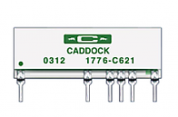
If you're willing to pay bigger bucks for more accuracy, the decade divider comes manufactured in a single package.

What are the benefits? Multiple resistors on a stick maintains better accuracy over temperature T. Say T rises causing a resistors to increase by some percentage. However, its neighbors - made from the same recipe and in close thermal contact - increases by the same amount! This means, of course, that the divider ratio stays the same. Slick idea.
DIVIDER IN ACTION
Let's apply some big voltages and see the decade divider in action. Voltage source VIN generates the input voltage. Resistors RDEC1-4 form the decade divider. Analog switches, RSW_0-3 select the voltage to be fed to the actual voltmeter. These switches have all been set to OPEN (or 1e12 ohms). Finally, RLP1 and CLP1 create a low-pass filter remove any unwanted high-frequency noise that may have coupled onto the voltage to be measured.
CIRCUIT INSIGHT Choose a maximum scale voltage like 20V, 200V or 2000V. Set VIN to this voltage. Run a TRANSIENT RESPONSE simulation and plot the voltage along the taps of the decade divider at V(52), V(53) and V(54). Are the voltages at each tap are smaller by 10x from the previous tap?
Given the VIN voltage you have set, which of the analog switches, RSW_0-3, should you set to 1 ohm in order to deliver the 2V max voltage to the voltmeter of the next stage? Set this switch to 1 ohm and rerun the simulation. Does the voltage at V(57) reach 2V max?
What is rise time to 90% of final value at the low-pass filter's output at V(58). Set CLP1 to 2x or 1/2x of the original value and check the effect on V(58)'s rise time.
DMM SERIES
Measure DC Volts with a Decade
Resistor Resistor Network.
Measure DC Current with a Decade
Current Sense Resistor Network.
Discover the heart of most DMM's - the
Dual-Slope Integrator.
SPICE FILE
Download the file or copy this netlist into a text file with the *.cir extension.
DMM_VDC_MEAS1.CIR
*
* INPUT VOLTAGE
VIN	51	0	200VDC
*
* DECADE DIVIDER
RDEC1	51	52	9E6
RDEC2	52	53	900K
RDEC3	53	54	90K
RDEC4	54	0	10K
*
* DIVIDER TAP SELECTOR SWITCHES - 1, 1/10, 1/100, 1/1000
RSW_0	51 57  1e12
RSW_1	52 57  1e12
RSW_2	53 57  1
RSW_3	54 57  1e12
*
* LOW-PASS FILTER
RLP1	57	58	200K
CLP2	58	0	1NF  IC=0V
*
* ANALYSIS *************************************************
.TRAN 	25US  10MS UIC
*.TRAN 	0.1US  2000US UIC*
.PROBE
.END
© 2013 eCircuit Center