Resistance Measure
CIRCUIT

DMM_R_MEAS1.CIR
Download
the SPICE file
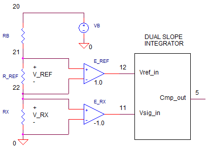
How do you measure resistance when the dual-slope integrator measures only voltage? This topic explores the ratio method.It harnesses the fundamental operation of the dual-slope integrator which creates a digital word using a ratio of an unknown voltage to a known reference voltage. We'll take advantage of this mechanism to find a ratio of an unknown resistance to a known resistance.
RESISTOR RATIO
The unknown resistance (Rx) is simply placed in series with a Reference Resistor (Rref). A bias voltage(VB)drives the series resistors causing a current to flow. What do we know about the ratio of V_Rx to V_Vref? It should be equal to the resistor ratios
= Rx / R_Ref
DUAL SLOPE INTEGRATOR
How do you connect these voltages to the dual-slope integrator inputs? As you might have guessed, V_Rx connects directly to the signal input, while V_Rref connects to the reference voltage input.
A quick recap of the dual-slope integrator might help here. Basically, the integrater has two phases
You typically use a counter to set T1 (fixed) and
measure T2 (variable).
The bottom line? The ratio T2 / T1 equals Vx / Vref so you could write
or, in terms of resistance
As an example, if you designed a DMM with T1=10ms, then for Rref=10k and a measured T2=7.5ms, you can deduce a measured resistance of
= 7.5k ohms
MEASURE IT
Enough talking, let's start simulating. VB creates a bias voltage for the resistor string. RB = 1k provides an additional series resistance to limit the current for low level measuremenbts (<100 ohm). Let say you've selected the 1 k ohm range. This means of course you need to set R_REF = 1k. Finally, set the unknown resistance to something like RX=900 ohms.
= Tfall - 10ms
For RX=900 ohms, where is the falling edge of V(5)? Uing the cursor, you find Tfall = 19.01ms which implies T1 = 19.01-10.0 = 9.01ms. The resistance is easily calculated as
= 1k *
9.01ms/10ms
= 901 ohms
A respectable result - nearly a 0.1% measuremt accuracy.
What happens when the ersistance gets too smalll? Try measureing RX near 100 ohms or 10 ohms. How accurate is the measurement? Might be best to switch to lower range. To do this, change R_REF to 100 or 10 ohms. How much did the accuracy improve?
SPICE FILE
DVM_RES_MEAS1.CIR
*
* VB
VB	20	0	9VDC
RB	20	21	1k
* R_REF
R_REF	21	22	1K
*
* RX - UNKNOWN RESISTOR
RX	22	0	10
*
* DIFF AMP - REFERENCE, R_RES
E_REF 12 0	21 22	+1.0
*
* DIFF AMP - UNKNOWN RES, RX
E_RX 11 0	22 0	-1.0
*
* CONTROL: VCNTRL=0 S1=ON, S2=OFF
*          VCNTRL=1 S1=Off,S2=ON
VCNTL	15	0	PWL(0MS 0V  10MS 0V 10.01MS 5V)
*
* INTEGRATOR
S1	11 1  15 0 SWB
S2	12 1  31 0 SWA
R1	1	2	100K
C1	2	3	0.10UF IC=0V
XOP1	0 2 3	OPAMP1
*
* COMPARATOR (ZERO CROSSING DETECTOR)
XCMP1	3 0 5 COMP1
*
* AND GATE, S2 = ON IF VCNTRL AND XCMP1 OUTPUTS ARE HI
VCC	30	0	DC	5V
R31	30	31	10k
D31 31	15	D1N4148
D32 31	5	D1N4148
*
*
* SUBCIRCUITS AND MODELS ***********************************
*
.SUBCKT COMP1  1 2 5
* TERMINALS: 1-INPUT+, 2-INPUT-, 5-OUTPUT
* DIFF AMP
EDIFF	3	0	VALUE = { V(1) - V(2) }
* FREQUENCY RESPONSE
RP1	3	4	500
CP1	4	0	1000PF
* LIMITER
EOUT	5	0	TABLE {V(4)} = (-0.5MV 0V) (0.5MV, 5V)
.ENDS
*
*
* OPAMP MACRO MODEL, SINGLE-POLE WITH 15V OUTPUT CLAMP
* connections:      non-inverting input
*                   |   inverting input
*                   |   |   output
*                   |   |   |
.SUBCKT OPAMP1	    1   2   6
* INPUT IMPEDANCE
RIN	1	2	10MEG
* DC GAIN=100K AND POLE1=100HZ
* UNITY GAIN = DCGAIN X POLE1 = 10MHZ
EGAIN	3 0	1 2	100K
RP1	3	4	100K
CP1	4	0	0.0159UF
* OUTPUT BUFFER AND RESISTANCE
EBUFFER	5 0	4 0	1
ROUT	5	6	10
.ENDS
*
.MODEL	SWA	VSWITCH(VON=5 VOFF=0 RON=1 ROFF=1e12)
.MODEL	SWB	VSWITCH(VON=0 VOFF=5 RON=1 ROFF=1e12)
*
* DIODE
.model	D1N4148	D(Is=0.1p Rs=16 CJO=2p Tt=12n Bv=100 Ibv=0.1p)
*
* ANALYSIS *************************************************
.TRAN 	25US  20MS UIC
*.TRAN 	0.1US  2000US UIC*
.PROBE
.END