Advanced SPICE Simulation
INTRO
Simulations typically start out with a sanity check of the basic topology (see Part 1.) Then more advanced models can be created by adding more details. A couple of things to keep in mind
- have a clear focus / goal of the simulation.
- verifying a spec, understanding a circuit, exploring a new idea, debugging a problem - all worthy of a simulation.
- don't overemphize non-essential details.
- Time spent on a multitude of tiny details may not reap a real benefit of more insight. Consider which complex behaviors are worth pursuing.
This simulation focuses more on learning then verifying specs. We'll perform basic measurements of 1.5V and 9V batteries, get familiar with the ADC's operation and the digital outputs that drive the input LED of analog switches. This preview prepares us for the actual lab testing of our DVM.
For an intro to the DVM simulations, goto Basic SPICE Simulation
Back to Design Series
SPICE CIRCUIT
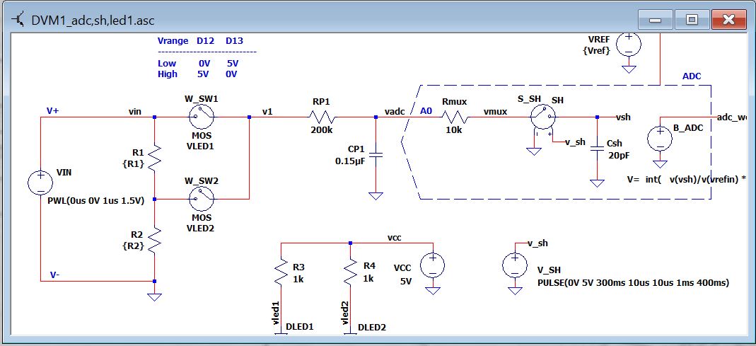
LTSPICE Schematic: DVM1_advanced1.asc
PSPICE Netlist: DVM1_advanced1_netlist.cir
Right Click on filename, select "Save link as...",
ADC FUNCTION
Let's include the Analog Input Multiplexer, Sample/Hold and ADC for this simple ADC model of the Arduino Analog inputs.
HOW IT WORKS
- Input Mux
- A resistor models the mux's ON resistance, Rmux = 10k
- Sample / Hold:
- A Voltage Controlled switch and capacitor captures the analog signal.
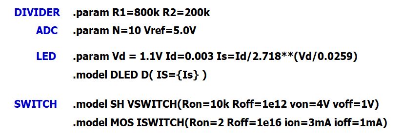
- Switch: .model SH VSWITCH(Ron=10k Roff=1e16 von=4V voff=1V)
- Cap: Csh = 20pF
- Sample / Hold Digital Drive
- A voltage source V_SH creates a pulse to close S/H switch at 0.3s for 1ms.
- PULSE(0V 5V 300ms 10us 10us 1ms 400ms)
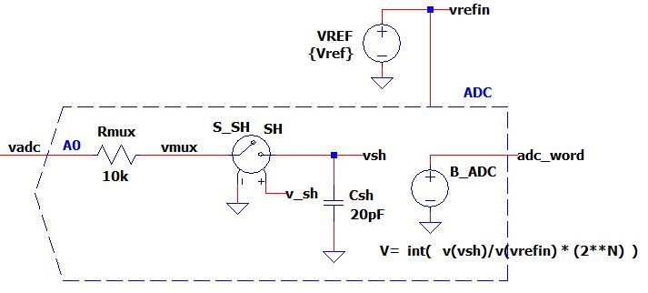
- ADC
- Ref and Resulution: .param N=10 Vref=5.0V
- A Behavioral Voltage B_ADC executes a mathematical expression for the digital output.
V = round( v(vsh)/v(vrefin) * (2**N) )
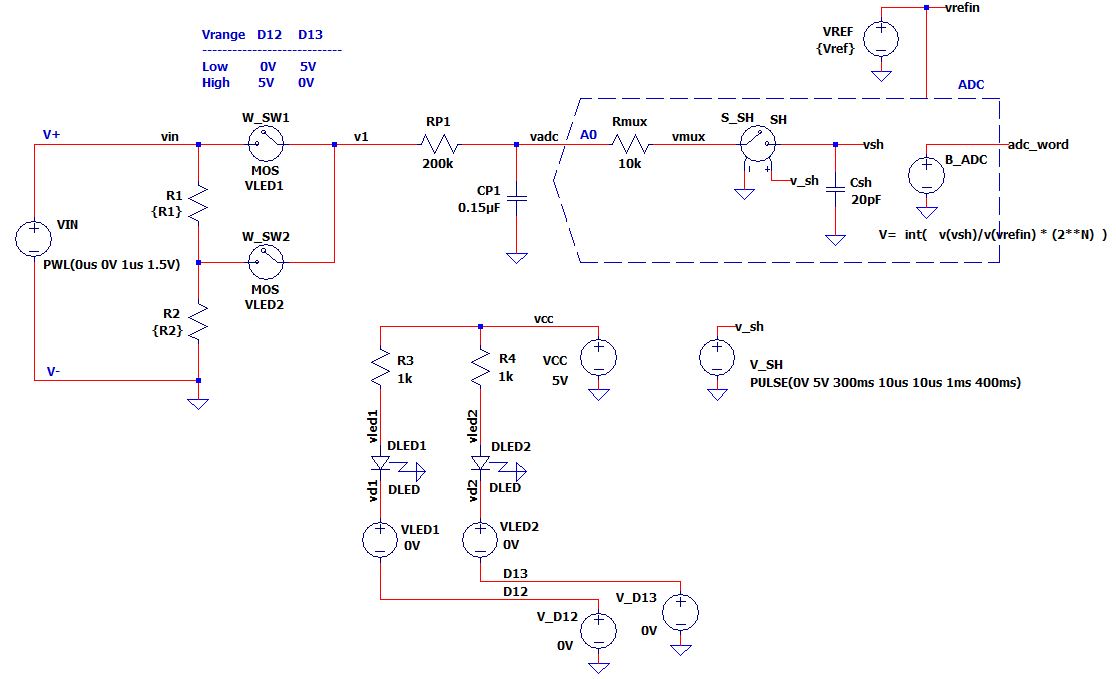
OPTO ISOLATED RELAYS
Also called a Photo MOS Switch, these devices Turn ON when sufficient current is driven through an input LED.
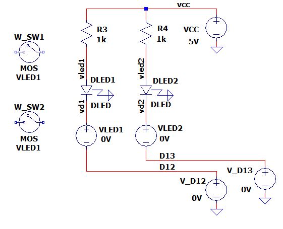
HOW IT WORKS
- Input LED
- A simple diode DLEDx models the LED voltage for a given
current.
.model DLED D( IS={Is} ) - IS sets the diode's voltage for a given current. Calculate IS via the diode equation:
.param Vd = 1.1V Id=0.003 Is=Id/2.718**(Vd/0.0259) - Current sense: VLEDx (0V voltage source) is used by the switches to sense the LED current
- A simple diode DLEDx models the LED voltage for a given
current.
- Photo-MOS Switch
- A Current Controlled Switch W_SWx turns ON to 2 ohms when 3mA of current flows through the LED (and VLEDx).
- model MOS ISWITCH(Ron=2 Roff=1e12 ion=3mA ioff=1mA)
- In reality, a fairly complex circuit operates between the LED current and the MOS switch. However, our simple model is only intended to verify that we've done our part with sufficient LED drive.
BATTERY MEASUREMENTS
Let's perform some basic measurements of the 1.5V and 9V batteries. We'll view the overall landscape regarding setup, voltage levels and ADC output.
SPECIFICATION: Battery Measurement, 1.5V.
SET INPUT AND CONDITIONS
- Input: Vin = 1.5V step input
- 4V Gain: K = 1.0 V/V
- 4V Select: D12=0V (SW1 On), D13=5V (SW2 Off)
SELECT OUTPUT AND MEASUREMENT
- Outputs: vadc, adc_word
- Measure: read vadc at final time
- Expected Values:
- vadc = Vin*K = 1.5V
- adc_word = vadc / Vrefin * 2^10
= 1.5V / 5.0V * 1024 = 307
RUN SPICE
- Vin step input: PWL(0s 0V 1us 1.5V)
- Time Analysis: .tran 0s 0.4s
MEASURE AND CHECK (adc_word)
- Error Limit: +/-2%
- Limits Lo, Hi: 303, 312
- Measured Value: ??? ⇒ PASS / FAIL?
SPECIFICATION: Battery Measurement, 9.0V.
SET INPUT AND CONDITIONS
- Input: Vin = 9.0V step input
- 4V Gain: K = 0.2 V/V
- 4V Select: D12=5V (SW1 Off), D13=0V (SW2 On)
SELECT OUTPUT AND MEASUREMENT
- Outputs: vadc, adc_word
- Measure: read vadc at final time
- Expected Values:
- vadc = Vin*K = 9V*0.2 = 1.8V
- adc_word = vadc / Vrefin * 2^10
= 1.8V / 5.0V * 1024 = 367
RUN SPICE
- Vin step input: PWL(0s 0V 1us 9V)
- Time Analysis: .tran 0s 0.4s
MEASURE AND CHECK (adc_word)
- Error Limit: +/-2%
- Limits Lo, Hi: 360, 377
- Measured Value: ??? ⇒ PASS / FAIL?
LED CURRENTS
The Photo-voltaic MOS relays require >3mA through the input LED to turn ON.
SPECIFICATION: PhotoMOS Relay, LED Current >3mA.
SET INPUT AND CONDITIONS
- Input: Vin = 1.5V step input (don't care)
- Both relays ON: D12=0V (SW1 On), D13=0V (SW2 On)
SELECT OUTPUT AND MEASUREMENT
- Outputs: LED currents
- Measure: read I(DLED1) and I(DLED2) at any time
- Expected Values: Iled = (Vcc-Vled)/Rled = (5.0-1.1V)/1k = 3.9mA
RUN SPICE
- Vin step input: PWL(0s 0V 1us 1.5V)
- Time Analysis: .tran 0s 0.4s
MEASURE AND CHECK
- Error Limit: +/-5%
- Limits Lo, Hi: 3.8mA, 4.1mA
- Measured Value: ??? ⇒ PASS / FAIL?
HANDS-ON TEST TRACKER
Play in the Excel file - modify values, see what happens!
- Excel File: DVM1_Simulation_Test_Tracker.xlsx
- Right Click on the filename, select "Save link as...".
Test Result Checker
- Record several of your simulation results in the column labeled "Measured Value".
- The Excel formula automatically checks it against the Hi and Lo Limits.
- Initially all tests FAIL because no data is entered. How many can you get to PASS?
DATA FOR SIMULATION
PhotoMOS Relay: TLP592A Datasheet
Arduino ADC (from Open Music Labs): ATmega328p ADC
NEXT UP
With two essential simulations completed, our confidence in our design has gone up a level!
Next, we can apply the powerful (and challenging) analysis tool to verify the circuit's accuracy - the Error Budget Analysis.
Or, in parallel, we can start the Software Design.
Back to Design Series