Part 1
Band-cut and Band-boost
LCR Filters
CIRCUIT

BANDCUT_BOOST_LCR.CIR Download the SPICE file
You see them everywhere Ė in home and car stereos, PA systems and guitar effect pedals - the Graphic Equalizer or EQ for short. Those wonderful controls, an array of multiple slide knobs alongside each other, can give you instant gratification of a boosted bass or crisper vocals and guitar. Hunting down a schematic on the web, I found the circuit operation was not immediately obvious. So it started a fun search for the reasons behind the circuit topology. There was a good guess that its foundation is built on the some form of LCR band-pass or band stop filters.
This topic begins a four part series in the design of a graphic equalizer circuit.
1. Band Cut & Boost - Series LCR
2. Cut & Boost - Single Pot
3. Band Cut & Boost - Series LCR and Pot.
4. Simulated Inductor and Graphic EQ
BANDCUT
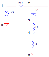
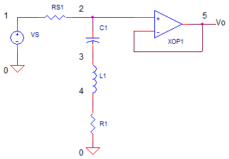
One of the simplest ways to make a bandcut filter is by creating an attenuator using a series LCR string.

The series leg has an impedance of Zseries = L1∑s + 1/(C1∑s) + R1.
How does this cut frequencies over a limited band of frequencies? Operation is simple Ė at frequencies far away from the center of the band, Zseries becomes large. Therefore, the attenuator made of RS1 and Zseries has a gain of unity, vo/vin = RS1/(Zseries + RS1) ė 1. However, at the resonant frequency

the impedance of the L and C cancel each other out (they are equal and opposite) and your left with Zsereies=R1. This creates an attenuation of vo/vin = R1/(R1+RS1). Youíll see the signal cut over a band of frequencies centered around fo.
Why the op amp? Itís there simply to buffer the signal and prevent the
impedance of the next stage from affecting the LCR behavior.
BANDBOOST
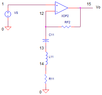
The bandboost is a variation on the bandcut circuit. The idea here is to
move the LCR leg to a strategic location for creating gain instead of
attenuation.

The LCR string has been moved to the gain components of the op amp. At
frequencies far away from fo, Zseries becomes large, creating a unity gain
op amp vo/vin = RF2 / Zseries + 1 = 1. However, at the resonant frequency fo,
the impedance of the L and C cancel each other out and youíre left with R1
only. This creates a gain vo/vin = RF2/R1 + 1. Youíll see the signal boost
over a band of frequencies centered around fo.
TUNED FILTER FEATURES
LCR tuned filters are described by several characteristics.
Center frequency, fo.
The center of the band, typically the peak of the frequency response curve.Bandwidth, BW = fH - fL.
The upper and lower frequencies, fH and fL, are defined as the frequencies where the gain has dropped to 0.707 of the mid-band gain.L and C Impedance.
The impedances of L and C are equal and opposite. The magnitudes are
Xc = 1 / (2∑ p ∑ fo ∑C ) and XL = 2∑ p ∑ fo ∑ LQuality factor, Q = fo / BW = XC/R = XL/R.
The Q tells you about the width of the pass-band:
Low Q → Wide bandwidth; High Q → Narrow bandwidth.Mid-band Gain, K = Vo / Vin.
This is voltage gain at the center frequency fo.
CIRCUIT DESIGN
Letís design the audio circuit for boost or cut of a about K=10x centered around
800 Hz. How wide should the bandwidth be? One reference for EQ design
(see below) suggests a bandwidth defined by a Q of about 1.7.
First, let's calc the resistor ratio needed for a boost/cut of 10x. Choose RS1=10k and calculate
R1 = RS1 / (K-1)
= 10k / (10-1) = 1.11k
Choosing a Q of 1.5 Letís let's calculate the impedance of C or L at fo. Note, R = R1 || RS1 = 1000.
X = R * Q = 1700
Finally, given X, find L and C
L = (2∑ p ∑ fo) / X∑= 338mH
C = 1 / (2∑ p ∑ fo ∑X )∑= 0.12 uFNOTE: You can adjust Q if needed to find values of L and C that are available from a manufacturer. You can also round the L and C the nearest available value. Just check that your circuit performance is still reasonably on target!
BANDCUT FILTER TEST
CIRCUIT INSIGHT Run
an AC Analysis of the the circuit named OP_BANDCUT_BOOST_LCR.CIR. Check out
the filter response by plotting the input V(1) and output V(5). Does the AC
response show a signal cut over a band of frequencies? Where is the center
of the dip? Did it hit the mark at 800 Hz?
From our equation above Q = fo / BW, you can rearrange it to predict the
bandwidth,
BW = fo/Q = 800Hz / 1.7 = 470 Hz. To measure the BW, move the cursor to
find the two frequencies where the gain falls -3dB (or, 0.707 times the
maximum response) on either side of the 800Hz.
HANDS-ON DESIGN Change the L or C value by a factor of 2 or 3. Did the center frequency shift up or down as expected? Now change R1. You should discover that the bandwidth changes, but the center frequency doesnít move.
BANDBOOST FILTER TEST
CIRCUIT INSIGHT
Check out the filter response by plotting the input V(1) and
output V(15).. Does the AC response show a signal boost over a band of
frequencies? Where is the center of the peak? Did it hit the mark at 800 Hz?
From our equation above Q = fo / BW, you can rearrange it to predict the
bandwidth,
BW = fo/Q = 800Hz / 1.7. To measure the BW, place a cursor to find
the two frequencies where the gain rises +3dB (or, 1.414 times the minimum
response) on either side of the 800Hz.
HANDS-ON DESIGN Change the L or C value by a factor of 2 or 3. Did the center frequency shift up or down as expected? Now change R1. You should discover that the bandwidth changes, but the center frequency doesnít move.
FINAL NOTES
EXCEL FILE
Nothing like an Excel file, "Bandcut_Boost_LCR.xls", to calculate components,
bandwidths and play with the numbers. Download a copy and modify it anyway
you like.
REFERENCE
ďAn
audio circuit collection, Part 3Ē from Texas Instruments.
NEXT UP
The next piece of the EQ circuit is a single op amp circuit that performs
both cut and boost functions. A single potentiometer sets the level of cut
or boost.
SPICE FILE
Download the file or copy this netlist into a text file with the *.cir extention.
* bandcut_boost_LCR.cir
*
VS	1	0	AC	1	SIN(0V 1V 800Hz)
*
* BANDSTOP
RS1	1	2	10000
C1	2	3	120NF
L1	3	4	0.33H
R1	4	0	1100
*
* OPAMP BUFFER
XOP1	2 5	5	OPAMP1
*
*
* BANDPASS
*
* OPAMP GAIN
XOP2	1	13	16	OPAMP1
RF1	13	16	10K
C11	13	14	120NF
L11	14	15	0.33H
R11	15	0	1000
*
* OPAMP MACRO MODEL, SINGLE-POLE
* connections:      non-inverting input
*                   |   inverting input
*                   |   |   output
*                   |   |   |
.SUBCKT OPAMP1	    1   2   6
* INPUT IMPEDANCE
RIN	1	2	10MEG
* GAIN BW PRODUCT = 1MHZ
* DC GAIN (100K) AND POLE 1 (10HZ)
EGAIN	3 0	1 2	100K
RP1	3	4	1K
CP1	4	0	15.915UF
* OUTPUT BUFFER AND RESISTANCE
EBUFFER	5 0	4 0	1
ROUT	5	6	10
.ENDS
*
* ANALYSIS *************************************
*.TRAN 	1us  100us
.ac dec 40 10 100k
.PROBE
.END
© 2011 eCircuit Center