ADC Input Driver
SINGLE-ENDED to
DIFFERENTIAL
CIRCUIT
ADCIN_SE_DIFF1.CR Download the SPICE file
The continuing story of input drivers brings us to the case where your signal source is single-ended, but your ADC accepts a differential input. For example, a position sensor that swings +/-10 V gets muxed to an ADC that expects a +/-4V differential input centered around 2 V. What's the solution? The Single-Ended to Differential Driver is your ticket to ride. To implement this circuit, we actually use a couple of Single-Ended to Single-Ended ADC Drivers we covered earlier. By mirroring the gains and choosing the right offset, you can properly feed your ADC's differential input!
TWO OF A KIND
From our first look of the Single-Ended to Single-Ended driver (assuming R2/R1 = R4/R3), we found that
Vo = Vin+ ∙ ( R2/R1 ) + Vin- ∙ ( -R2/R1 ) + VREF
This circuit gives you the choice of connecting your signal Vsig to either Vin+ or Vin- (and grounding the other) providing you with either a non-inverting or inverting amplifier. So let's take two of these circuits and generate two outputs of opposite polarity.
Amplifier 1: Non-Inverting
Vo+ = Vsig ∙ ( R2/R1 ) + VREF
Amplifier 2: Inverting
Vo- = Vsig ∙ ( -R2/R1 ) + VREF
All that's left is choosing the proper gain/attenuation (K = R2 / R1) for each amplifier and the offset (VREF).
HOW MUCH GAIN AND OFFSET?
The main thing to remember is that each amplifier will provide half of the required gain. Back to our original challenge: a sensor generates a ±10 V single-ended signal will ultimately feed an ADC that expects ±4 V differential centered around 2 V. How much gain/attenuation do you need for each amplifier?
K = ( ±4 V / ±10 V ) · 1/2
= 0.2 V/V
Choosing R2 = 10 kΩ, calculate R1 from the gain equation K = R2/R1
R1 = R2 · K
= 10 kΩ · 0.2
= 2 kΩ.
For an offset of 2 V, simply set VREF to this level.
TEST DRIVE
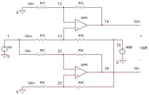
The SPICE file has two amplifiers XOP1 (with R11, R12, R13, R14) and XOP2 (with R21, R22, R23, R24) wired as a non-inverting and inverting amplifier, respectively. The gains are set by
K = R2 / R1
= R12 / R11 = R14 / R13
= R22 / R21 = R24 / R23
HANDS-ON DESIGN
Start with
these initial
values: all Rs = 10k (K=1) and VREF = 0 V. Run a simulation of
ADCIN_SE_DIFF1.CIR. Plot the input V(1) and both the positive and negative
output, V(14) and V(24). In a separate window, plot the differential output
that the ADC would see,
V(14) - V(24). You should see input/outputs swing ±10V
while the differential output swings ±
20V! Cool, you get twice the swing from a differential output! But,
we're not there yet!
Now adjust the individual amplifier gain to 0.2 by changing R12 = R14 = R22 = R24 = 2 k. Rerun the simulation and check the differential output. Yes, you've got the desired +/- 4V differential swing. BUT, each output swings positive and negative! Not good for an ADC that runs from a single +5 V rail.
Now set VREF = 2.0 V and rerun the SPICE file. Any improvement? Yes, each output gets shifted by 2 V for a total swing between 0 and 4 V. Good news for the ADC input! Did this shift have any effect on the differential output V(14)-V(24)? More good news, VREF has no effect on the differential gain. Looks like our circuit is ready to roll.
NEW SENSOR
HANDS-ON DESIGN A new sensor has been dropped in your system. This device swings ±1 V in response to a ± tilt angle. The ADC input expects ±5 V differential centered around 2.5 V. Start with these initial values: all Rs = 10k (K=1) and VREF = 0 V. Change the source for 1 V peak
VS1 1 0 SIN(0V +1VPEAK 1KHZ)
What values of gain resistors and VREF will make the ADC input happy?
MORE TOPICS
Here's around-up of the ADC driver topics to explore.
Single-Ended Input to Single-Ended Output
Differential Input to Single-Ended Output
Single-Ended Input to Differential Output
Differential Input to Differential Output
The last two functions require a couple of op amps. However, take a look at a single device - the Fully Differential Amplifier - that performs the functions.
SIMULATION NOTES
For a more detailed description of the op amp, see the Basic Op
Amp
Model.
For a quick review of subcircuits, check out Why Use Subcircuits?
Get a crash course on SPICE simulation at
SPICE Basics.
A handy reference is available at SPICE
Command Summary.
Browse other circuits available from the Circuit
Collection page.
SPICE FILE
Download the file or copy this netlist into a text file with the *.cir extension.
ADCIN_SE_DIFF1.CIR - SINGLE-ENDED TO DIFFERENTIAL ADC INPUT DRIVER
*
VS1	1	0	SIN(0V	10VPEAK	1KHZ)
VREF	10	0	DC	0V
*
* NON-INVERTING OUTPUT
R11	0	12	10K
R12	12	14	10K
R13	1	13	10K
R14	13	10	10K
XOP1	13 12	14	OPAMP1
*
* INVERTING OUTPUT
R21	1	22	10K
R22	22	24	10K
R23	0	23	10K
R24	23	10	10K
XOP2	23 22	24	OPAMP1
*
*
* SINGLE-POLE OPERATIONAL AMPLIFIER MACRO-MODEL
* connections:      non-inverting input
*                   |   inverting input
*                   |   |   output
*                   |   |   |
.SUBCKT OPAMP1	    1   2   6
* INPUT IMPEDANCE
RIN	1	2	10MEG
* DC GAIN (100K) AND POLE 1 (100HZ)
* GBWP = 10MHZ
EGAIN	3 0	1 2	100K
RP1	3	4	1K
CP1	4	0	1.5915UF
* OUTPUT BUFFER AND RESISTANCE
EBUFFER	5 0	4 0	1
ROUT	5	6	10
.ENDS
*
.TRAN 	0.01MS  2MS
*
.PLOT	TRAN 	V(1) V(14) V(24)
.PRINT	TRAN 	V(1) V(14) V(24)
.PROBE
.END
© 2006 eCircuit Center