Thermocouple Preamp
CIRCUIT
TC_PREAMP1.CIR Download the SPICE file
We already developed the thermocouple's SPICE model. Now let's create a practical circuit using this popular sensor. Because the actual voltage is small, you need a lot of gain to make this signal big enough to pass to an ADC. The other tricky bit is that the measurement depends on the temperature both at point of interest (measure junction) AND the where the thermocouple connects to your circuit (reference junction). Because the reference junction will change with room temperature, you need to compensate for these changes (cold-end compensation).
Armed with a thermocouple, a local temp sensor and a summing amplifier you can design a practical preamplifier. As a project goal, let's design a circuit for a J-Type thermocouple that produces a 0 to 100 mV output for a 0 to 100 deg C temperature change - effectively, an output of 1 mV / C.
SUMMING AMPLIFIER
What circuit can juggle the multiple functions required by the thermocouple preamp? The summing amplifier is perfect for accomplishing these three functions.
1. Amplify the thermocouple signal.
2. Subtract the effect of the reference junction at room temperature.
3. Add an offset adjustment.
The summing amplifier is nice because you can adjust each input independently using input resistors R1, R2 and R3.
Vo = (-RF/R1) · V1 + (-RF/R2) · V2 + (-RF/R3) · V3
Let's design a circuit to accomplish these three functions above using three simple steps.
STEP 1. THERMOCOUPLE GAIN
How much gain is needed to generate a 100mV for 100 deg C temp change? First, find how much voltage Vtc the thermocouple produces. Although it's somewhat nonlinear over a large temp range, calculate the average temperature coefficient for a J-Type thermocouple over 100 deg C.
dV/dT = [Vtc(100) - Vtc(0)] / [100 deg C - 0 deg C ]
= [5.269 mV - 0 mV ] / 100 deg C= 52.69 uV / deg C
Given this coefficient and a target output of dVo/dT = 1 mV / deg C, we calculate the gain K1 needed.
K1 = (dVo/dT) / (dVtc/dT) = (1mV / C) / (52.69uV / C) = 18.98 V/V
All that remains is finding R1 to achieve the gain. First choose RF to be 100k (you can always choose a different value if the other resistors are not practical or available.) Then, calculate R1
R1 = RF / K1 = 100k / 18.98 = 5269 ohms.
Remember the summing amp is inverting! To get a positive output, connect the neg side of the thermocouple to the amplifier input.
STEP 2. COLD-END COMPENSATION
A major thorn in the side of a thermocouple measurement is that they don't measure the absolute temperature of the junction. However, they do measure the temperature difference between the measure junction Tjunc and the reference junction Tref. So what happens if Tjunc = 100 C and Tref (room temperature) increases from 22 C to 23 C. The difference changed from 100 C - 22C = 78 deg C to only 100 C - 23 C = 77 deg C! Accordingly, the thermocouple voltage changed proportionately by -1 deg C even though the measure junction did not change! Correspondingly, the preamp's output will change by -1 mV.
To compensate for this decease in voltage, you need to add a voltage to the output that's proportional to +1 deg C = +1 mV. To accomplish this feat, simply place a local temperature sensor close to the reference junction. Then, use the summing amp to get +1mV output for every deg C of local temp change.
For this design, we've chosen an LM335 IC. This sensor produces a voltage change of +10mV / deg C. ( Actually the sensor operates in Kelvin, 0 deg C = 273 K, generating an output at 22 C of Vsensor = (273 + 22) C * 10mV/C = 2.95 V.) So how much gain do we need to transform 10mV / C into 1 mV/deg C?
K2 = (dVo/dT) / (dVsensor/dT) = (+1mV / C) / (+10 mV/ C) = 0.1 V/V
Then, calculate R2
R2 = RF / K2 = 100k / 0.1 = 1000k ohms.
Again, because the summing amp is inverting and we need a +1mV/C at the output, connect the sensor's negative terminal to V2. The upshot of this is V2 = -10mV/C and Vo2 = +1mV/C. The only challenge left is subtracting the sensor offset of 2.95V.
STEP 3. ADD OFFSET VOLTAGE
For the final step, we need to subtract the large offset of the local temp (-2.95V) and accurately adjust the output for the correct temperature. This fairly easy step involves picking a specific measurement and reference temperature, then using our summing amp equation to find the offset voltage Voff required at V3. (Voff is typically implemented with a potentiometer.)
Our grand equation looks like
Vo = (-RF/R1) · V1 + (-RF/R2) · V2 + (-RF/R3) · V3
(-RF/R1) · Vtc + (-RF/R2) · Vsensor + (-RF/R3) · Voff
All that remains is choosing R3 and rearranging the equation to find Voff.
Voff = ( Vo + (RF/R1)·Vtc + (RF/R2)·Vsensor ) / ( -RF/R3 )
To make our calculation easier, let's choose the Tjunc = 22 and Tref = 22 C. Why is this easier? With the Tjunc == Tref, the thermocouple output is zero, Vtc = 0 mV. Let's substitute what we know and choose R3 = 1000k. Given our design goal of 1mV/C, we expect 22mV at the output.
22mV = (-100k/5200) · 0mV + (-100k/1000k) · -2.95V + (-100k/1000k) · Voff
= (-100k/1000k) · -2.95V + (-100k/1000k) · Voff
Rearranging the equation we get
Voff = ( Vo + (RF/R2) · Vsensor ) / (-RF/R3)
= ( 22mV + (100k/1000k) · -2.95V ) / (-100/1000k)
= +2.73 V
Question: can you easily generate Voff with an available reference voltage and a potentiomemter? Imagine for this design we have a Vref = +5V and a 5k ohm pot connected from 5V to ground - piece of cake! The wiper of the pot can be adjusted from 0 to 5V. However, if your Voff was greater than Vref, you could choose a different R3 such that Voff < Vref.
SPICE CIRCUIT
Here's the SPICE circuit of the thermocouple preamp.
To simulate the measure junction temperature Tjunc at V(10) and reference junction temperatures Tref at V(11), we'll use two voltage sources where V really represents T in deg C. The Piece-Wise Linear (PWL) sources will linearly ramp the temperatures over a 100ms interval.
V_TJUNC 10 0 PWL(0MS 0 100MS 100)
V_TREF 11 0 PWL(0MS 22 100MS 22)
Initially, we'll sweep Tjunc from 0 to 100 deg C while keeping Tref fixed at 22 deg C. These voltages (temperatures) feed the thermocouple defined by a subcircuit (See TC model) . The negative terminal connects to R1.
X_TC1 10 11 0 1 TC_J_1
The cold-end compensation is achieved by a local temperature sensor (LM335 IC) modeled simply as a Voltage Controlled Voltage Source (VCVS) at V(11). An equation describes it's V vs. T behavior of +10 mV / K where 273 K = 0 deg C. Similar to the thermocouple, the negative terminal connects to R2.
E_VSENSOR 0 2 VALUE = { 2.73 + V(11)*0.010 }
A simple voltage source creates the offset
VOFF 3 0 DC 2.73
Finally, our op amp SPICE model is a simple one capturing it's open-loop gain and gain-bandwidth product.
XOP1 0 4 5 OPAMP1
Learn more about the basic SPICE op amp model here.
SPICE SIMULATION
Let's see if our calculations actually mean something. We'll simulate operation from 0 to 100 deg C with the reference junction held at 22 C (room temperature).
CIRCUIT INSIGHT Run a simulation of TC_PREAMP1.CIR. Plot Tjunc at V(10) and Tref at V(11). Open a second window and plot the thermocouple output at V(1). Open a third window and plot the preamp output at V(5). Does the output match the expected 0 to 100 mV? The preamp's output should be within a mV of the target value.
Actually, because we calculated Voff at conditions Tjunc = Tref = 22 deg C, the output should be spot on at this temperature. Move your cursor to around 22 deg C. How accurate is the output in mV? Because the thermocouple is a non-linear device, (requiring an 8th order polynomial to approximate it's output), the accuracy falls off as you move away from the 22 deg C adjustment point.
Finally, let's put our cold-end compensation to the test! Keep Tjunc fixed at 100 deg C and sweep Tref (room temperature) from 10 to 40 deg C. How well does the local temp sensor and circuitry keep the measurement steady? Rerun the simulation and check V(5). Did the output hover near 100 mV as the room temperature swung through it's expected range? Seeing the cold-end compensation was the big payoff for me. You can see the thermocouple V(1) changing with room temperature while the local sensor (open a new window and plot V(2) ) was moving in the opposite direction to cancel the effect!
THE REAL DEAL
This was a marathon topic - high fives for staying the course! Just a few closing notes. To get a highly accurate reading over a large temperature swing, many systems use calibration and software to linearize the highly non-linear output of a thermocouple. These T vs. V equations are typically published with the V vs. T equations used to create the SPICE model.
The gain resistor R1=5269 will not likely be a standard resistor value. But you can always use a potentiometer or a parallel/series combination to get very close.
Also, you'll find the local sensor for cold-end compensation comes in many forms - IC sensor, thermistor, diode, Vbe junction. Which ever is used, simply choose the polarity and apply a gain such that it's output cancels thermocouples change due to local junction temperature change. In a real circuit, the local sensor LM335 needs a bias resistor not shown in the simulation. We didn't need one because our simplified SPICE model used a voltage source defined by an equation.
A friend of mine designed and bread-boarded a preamp circuit for the K thermocouple.
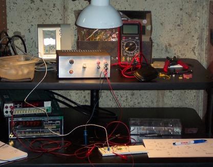
He added a gain adjust (potentiometer) for R2 as well as one for the offset adjust voltage Voff. For calibration, he used two handy temperature references inside every house - a container of ice cubes and a pot of boiling water. Thank you Mike for the picture of the home lab.
LINKS
Here's an excel file that will take you through the
thermocouple preamp calculations.
For a detailed description of the opamp, see the Basic Opamp
Model and Why Use Subcircuits?
Learn more about functions like VALUE in Analog Behavioral Modeling.
Learn how to develop a thermocouple's SPICE
model.
Find thermocouple tables and coefficients at the
TC
Tables and Coefficients index page.
Here are direct
download links from the NIST data base files. (NOTE: Files have the extension *.tab, but are in ASCII format.
Can be easily renamed
to *.txt or *.asc )
All
Thermocouple Types in ASCII or text format (NIST WEB file) (131K)
Type
B Thermocouple(19K)
Type
E Thermocouple(14K)
Type
J Thermocouple(16K)
Type
K Thermocouple(18K)
Type
N Thermocouple(17K)
Type
R Thermocouple(20K)
Type
S Thermocouple(20K)
Type
T Thermocouple(9K)
SPICE FILE
Download the file or copy this netlist into a text file with the *.cir extention.
TC_PREAMP.CIR - THERMOCOUPLE PREAMPLIFIER
*
* T MEASURE JUNCTION (deg C)
V_TJUNC	10	0	PWL(0MS 0	 100MS 100)
RD10	10	0	1MEG
*
* T REFERENCE JUNCTION (deg C)
V_TREF	11	0	PWL(0MS 22	 100MS 22)
RD11	11	0	1MEG
*
* J THERMOCOUPLE (V)
X_TC1	10 11 0 1	TC_J_1
R1	1	4	5269
*
* COLD JUNC - IC TEMP SENSOR (10MV/ DEG K)
E_VSENSOR 0	2	VALUE = {  2.73 + V(11)*0.010 }
R2	2	4	1000k
*
* OFFSET VOLTAGE
VOFF 3	0	DC	2.73
R3	3	4	1000K
*
* FEEDBACK R
RF	4	5	100K
*
* OPAMP
XOP1	0 4	5	OPAMP1
*
*
*** J THERMOCOUPLE SUBCIRCUIT ************************************
*	T_JUNC(C) - 1    T_REF(C) - 2   V_TC+(V) - 3  V_TC-(V) - 4
*
.SUBCKT TC_J_1	1 2  3 4
*
* USE POLYNOMIAL EQN TO FIND V VS. T (REF TO 0 DEGC) AT BOTH JUNC AND MEAS TEMPS.
*    V = B1*T + B2*T^2 + ...
*
*  V_TJ - JUNCTION EMF (MV) VS. TEMP (C)
E_TJ 5 0 VALUE = {
+   0.503811878150E-01*V(1)    +   0.304758369300E-04*V(1)**2 +
+  -0.856810657200E-07*V(1)**3 +   0.132281952950E-09*V(1)**4 +
+  -0.170529583370E-12*V(1)**5 +   0.209480906970E-15*V(1)**6 +
+  -0.125383953360E-18*V(1)**7 +   0.156317256970E-22*V(1)**8   }
*
* V_TR - REFERENCE EMF (MV) VS. TEMP (C)
E_TR 6 0 VALUE = {
+   0.503811878150E-01*V(2)    +   0.304758369300E-04*V(2)**2 +
+  -0.856810657200E-07*V(2)**3 +   0.132281952950E-09*V(2)**4 +
+  -0.170529583370E-12*V(2)**5 +   0.209480906970E-15*V(2)**6 +
+  -0.125383953360E-18*V(2)**7 +   0.156317256970E-22*V(2)**8   }
+
* THERMOCOUPLE OUTPUT:
* V_TC = V_TJ - V_TR
* DIVIDE BY 1000 TO CONVERT MV TO V
*
E_TC	3	4	VALUE = { (V(5)-V(6))/1000 }
*
.ENDS
******************************************************************
*
* OPAMP MACRO MODEL, SINGLE-POLE
* connections:      non-inverting input
*                   |   inverting input
*                   |   |   output
*                   |   |   |
.SUBCKT OPAMP1	    1   2   6
* INPUT IMPEDANCE
RIN	1	2	10MEG
* GAIN BW PRODUCT = 10MHZ
* DC GAIN (100K) AND POLE 1 (100HZ)
EGAIN	3 0	1 2	100K
RP1	3	4	1K
CP1	4	0	1.5915UF
* OUTPUT BUFFER AND RESISTANCE
EBUFFER	5 0	4 0	1
ROUT	5	6	10
.ENDS
****************************************************************
*
* ANALYSIS
.TRAN 	1MS  100MS
* VIEW RESULTS
.PROBE
.END
© 2009 eCircuit Center