Thermocouple SPICE Model
CIRCUIT

THERMOCOUPLE.CIR Download the SPICE file
What if you were asked to design a temperature sensor to measure 500 deg C - which sensor would you choose? A likely candidate is the thermocouple. On the up side it has a large temperature measurement range. On the down side, you've got a small signal versus temperature. To complicate matters, the exact output voltage depends on the temperature where the thermocouple connects to your circuitry (cold end).
This topic concentrates on the developing a SPICE model for the thermocouple itself. It's pretty straightforward, but takes a little math to get there. Another topic shows how to amplify the signal and compensate for the cold end junction temperature.
(In another topic, we'll design a thermocouple preamp.)
THERMOCOUPLE BASICS
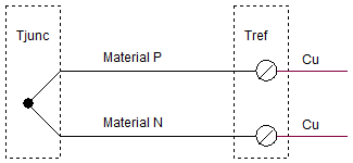
The basic thermocouple is made of two different types of metals.

They are joined to form the measurement junction: You put this end into your oven or deep freezer where you need to measure the temperature. The two free ends of the thermocouple connect to your circuit at the reference junction. The copper pads at the connection point have no effect on output voltage if they are both held at Tref.
Ideally, you stick the reference junction into an ice bath (Tref=0 deg C). The output of the thermocouple has been characterized under these conditions. You can find the output (typically in mV versus deg C) in the form of a table or coefficients of an 8th order polynomial.
V(T) = a1·T + a2·T2 + a3·T3 + . . . + a8·T8
However, it's not very practical or economical to place the reference junction in an ice bath.
Let's find the thermocouple output Vtc with the measurement junction at Tjunc and the reference junction at Tref=Troom.
To get a gut feel for this, assume initially that Tjunc=100 deg C and Tref = 0 deg C. The thermocouple acts on the difference between these temps (Tjunc - Tref = 100 - 0 = 100 ) to generate an output.
Vtc = Vjunc@100
You can use the polynomial equation with Tref in an ice bath. But, what if the reference junction is at room temperature Tref = 22 deg C? Now the difference between the Tjunc and Tref has been reduced to (100 - 22 = 78). Consequently, the thermocouple output will also be reduced! To find the new output, use this equation
Vtc = Vjunc@100 - Vref@22
where both voltages are calculated using same polynomial with an ice bath reference.
THE SPICE MODEL
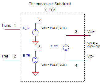
The thermocouple subcircuit is straight forward.

Two Voltage-Controlled-Voltage-Sources (VCVS) named E_TJ and ETR generate the voltage output (mV) for the Tjunc and Tref inputs at nodes 1 and 2. The polynomial coefficients describe the TYPE-J thermocouple for the range of -210 to 760 deg C. (You can download the TYPE-J table and coeff text file. See info on coefficients for all thermocouples below.) The output E_TC at nodes 3 and 4 takes the difference between E_TJ and E_TR, then divides by 1000 to convert the mV output into V.
Here's the netlist.
*** J THERMOCOUPLE SUBCIRCUIT ************************************
*	T_JUNC(C) - 1    T_REF(C) - 2   V_TC+(V) - 3  V_TC-(V) - 4
*
.SUBCKT TC_J_1	1 2  3 4
*
* USE POLYNOMIAL EQN TO FIND V VS. T (REF TO 0 DEGC) AT BOTH JUNC AND MEAS TEMPS.
*    V = B1*T + B2*T^2 + ...
*
*  V_TJ - JUNCTION EMF (MV) VS. TEMP (C)
E_TJ 5 0 VALUE = {
+   0.503811878150E-01*V(1)    +   0.304758369300E-04*V(1)**2 +
+  -0.856810657200E-07*V(1)**3 +   0.132281952950E-09*V(1)**4 +
+  -0.170529583370E-12*V(1)**5 +   0.209480906970E-15*V(1)**6 +
+  -0.125383953360E-18*V(1)**7 +   0.156317256970E-22*V(1)**8   }
*
* V_TR - REFERENCE EMF (MV) VS. TEMP (C)
E_TR 6 0 VALUE = {
+   0.503811878150E-01*V(2)    +   0.304758369300E-04*V(2)**2 +
+  -0.856810657200E-07*V(2)**3 +   0.132281952950E-09*V(2)**4 +
+  -0.170529583370E-12*V(2)**5 +   0.209480906970E-15*V(2)**6 +
+  -0.125383953360E-18*V(2)**7 +   0.156317256970E-22*V(2)**8   }
+
* THERMOCOUPLE OUTPUT:
* V_TC = V_TJ - V_TR
* DIVIDE BY 1000 TO CONVERT MV TO V
*
E_TC	3	4	VALUE = { (V(5)-V(6))/1000 }
*
.ENDS
The VALUE functions implement the polynomials for the thermocouple voltages at E_TJ and E_TR.
E{name} {+node} {-node} VALUE {expression}
This function will produce a voltage at output nodes +node and -node described by the mathematical expression. The actual expression uses a couple of SPICE tricks. First, the power operator, 23 for example, gets implemented by "**" as in "2**3". (This syntax seems to comes from the old FORTRAN programming days.) Second, for readability you can distribute a long SPICE command over a few lines by using the "+" character at the beginning of the next line. This tells SPICE to append the line to the previous one. The append feature helped manage the polynomial equations.
The SPICE model is a simplified version that captures the basic thermocouple function. It does not include internal resistance (you could add this as a series resistor) or self heating effects if large amounts of current flow through the sensor (very unusual).
THERMOCOUPLE TEST
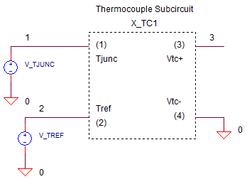
Two voltage sources (we know it's really deg C) represent the Tjunc and Tref in deg C.
V_TJUNC 1 0 PWL(0MS 22 100MS 100)
V_TREF 2 0 PWL(0MS 0 100MS 0)
The voltages are defined by Piece-Wise-Linear (PWL) segments. V_TJUNC starts at 22V (we know its deg C) and then ramps to 100V at 100 ms. Initially, V_TREF sits in an ice bath with its voltage set at 0 deg C. From the TYPE-J tables and coeff text file, let's pick a few temperatures to test
T(C) V(mV)
22 1.122
100 5.269
500 27.393
760 42.919
CIRCUIT INSIGHT
Run a simulation of the SPICE file THERMOCOUPLE.CIR. Plot
V_TJUNC at V(1) and V_TREF at V(2). Open another plot window to plot the
thermocouples output at V(3).
Behind the scenes, the SPICE math machine crunched a lot of coefficients
and inputs to get the output!
Check the output V(3) at temperatures V(1)=22 and 100. Is it close to the 1.122 mV and 5.269 mV listed in the table above? You can change the PWL statement for V_TJUNC for values like 500 or 760 to test other temperatures.
Now, set the junction temperature to be fixed at 100, and let's change the reference temperature from 0 to 22.
V_TJUNC 1 0 PWL(0MS 100 100MS 100)
V_TREF 2 0 PWL(0MS 0 100MS 22)
Rerun the simulation and check the output V(3). You should see 5.269 mV with Tref at 0. But what happens to V(3) when Tref reaches 22 deg C? According to our model, the thermocouple sees a smaller temperature difference and will output a smaller voltage. You can calculate the expected output as 5.269 mV (100 deg C) minus 1.122mV (22 deg C).
PREAMP AND COMPENSATION
If Tref = Room Temperature, then a changing ambient temperature can certainly cause you grief by mucking up the direct reading of the thermocouple. In another topic, we'll design a thermocouple preamp that compensates for this changing Tref with a local temperature sensor and a summing amp.
.
TABLES AND COEFFICIENTS
Tables of mV vs. temperature and polynomial coefficients can be directly downloadable from the NIST online data base. (NIST: the National Institute of Standards and Technology.)
TC Tables and Coefficients Index page at NIST that includes the definitions and formats for the various tables and coefficients.
Here are direct
download links from the NIST data base files. (NOTE: Files have the extension *.tab, but are in ASCII format.
Can be easily renamed
to *.txt or *.asc )
All
Thermocouple Types in ASCII or text format (NIST WEB file) (131K)
Type
B Thermocouple(19K)
Type
E Thermocouple(14K)
Type
J Thermocouple(16K)
Type
K Thermocouple(18K)
Type
N Thermocouple(17K)
Type
R Thermocouple(20K)
Type
S Thermocouple(20K)
Type
T Thermocouple(9K)
MORE INFORMATION
Design a thermocouple preamplifier using
an op amp summing amplifier.
Learn more about functions like VALUE in Analog Behavioral Modeling.
Review SPICE
Subcircuits at the SPICE Basics page.
SPICE FILE
Download the file or copy this netlist into a text file with the *.cir extention.
THERMOCOUPLE.CIR
*
* T MEASURE JUNCTION (deg C)
V_TJUNC	1	0	PWL(0MS 22	 100MS 100)
R1	1	0	1MEG
*
* T REFERENCE (deg C)
V_TREF	2	0	PWL(0MS 0	 100MS 0)
R2	2	0	1MEG
*
* J THERMOCOUPLE (V)
X_TC1	1 2 3 0	TC_J_1
R3	3	0	1MEG
*
*
*
*** J THERMOCOUPLE SUBCIRCUIT ************************************
*	T_JUNC(C) - 1    T_REF(C) - 2   V_TC+(V) - 3  V_TC-(V) - 4
*
.SUBCKT TC_J_1	1 2  3 4
*
* USE POLYNOMIAL EQN TO FIND V VS. T (REF TO 0 DEGC) AT BOTH JUNC AND MEAS TEMPS.
*    V = B1*T + B2*T^2 + ...
*
*  V_TJ - JUNCTION EMF (MV) VS. TEMP (C)
E_TJ 5 0 VALUE = {
+   0.503811878150E-01*V(1)    +   0.304758369300E-04*V(1)**2 +
+  -0.856810657200E-07*V(1)**3 +   0.132281952950E-09*V(1)**4 +
+  -0.170529583370E-12*V(1)**5 +   0.209480906970E-15*V(1)**6 +
+  -0.125383953360E-18*V(1)**7 +   0.156317256970E-22*V(1)**8   }
*
* V_TR - REFERENCE EMF (MV) VS. TEMP (C)
E_TR 6 0 VALUE = {
+   0.503811878150E-01*V(2)    +   0.304758369300E-04*V(2)**2 +
+  -0.856810657200E-07*V(2)**3 +   0.132281952950E-09*V(2)**4 +
+  -0.170529583370E-12*V(2)**5 +   0.209480906970E-15*V(2)**6 +
+  -0.125383953360E-18*V(2)**7 +   0.156317256970E-22*V(2)**8   }
+
* THERMOCOUPLE OUTPUT:
* V_TC = V_TJ - V_TR
* DIVIDE BY 1000 TO CONVERT MV TO V
*
E_TC	3	4	VALUE = { (V(5)-V(6))/1000 }
*
.ENDS
*
*
* ANALYSIS
.TRAN 	0.1MS  100MS
*
.PROBE
.END
© 2009 eCircuit Center