Source Measure Unit (SMU)
Basic Circuit
Schematic Overview and SPICE Simulation
Download SPICE Netlist or LTSPICE
Schematic
Right Click on filename, select "Save link as..."
Let's create a Source Measure Unit (SMU) using analog circuits.
You'll see classic op amp and inamp circuits bring the block diagram to life.
With a hands-on SPICE model and Excel Design File, you can develop some
deeper understanding and intuition.
SMU Specifications
- Force Voltage: +/- 5V
- Force Current: +/- 10mA
- Current Sense Voltage: Vs = +/-1V max
Back to SMU Series
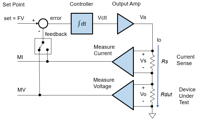
BASIC BLOCKS
SMUs implement classic voltage / current feedback loops. Get a review of the basic blocks.
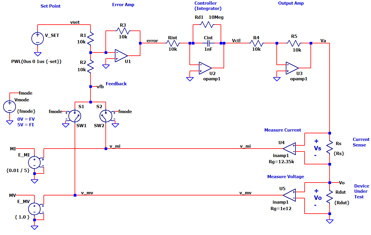
SCHEMATIC OVERVIEW
The schematic sections transform each of the basic blocks into an analog circuit. Many circuit possibilities exist! Here are some typical implementations.
SIGNAL LEVELS
Voltage levels in a control loop are typically defined by the system's DAC and ADC voltage ranges.
- Set point signal vset is driven by a DAC Output: Vdac = +/- 5V
- Measure signals v_mv, v_mi are fed to ADC Inputs: Vadc = +/- 5V
SET LEVEL
The set level is modelled with a simple Voltage Source (V_SET) representing the system DAC. (See SPICE Details below).
ERROR AMPLIFIER
The Error Amplifier (or Summing Junction in control terms) gets implemented by a Summing Op Amp config.
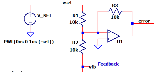
verror = - V1∙(R3/R1) - V2∙(R3/R2)
By setting R1=R2=R3=10k, v1 = -vset and v2 = vfb we get
verror = (set - vfb)
CONTROLLER (INTEGRATOR)
The classic op amp integrator keeps a running sum of the error scaled by Kint
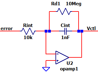
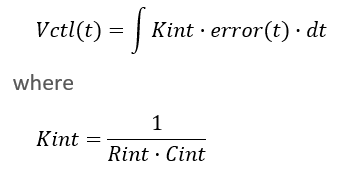
For a larger error, Vctl rises more rapidly toward the desired
value.
For a smaller error, Vctl rises more slowly toward the
desired value.
Need to adjust the speed? Cranking Kint UP or DOWN makes the force loop respond FASTER or SLOWER.
OUTPUT AMPLFIER
An Inverting Amp delivers the required output voltage and current. Typically a power op amp is selected to deliver larger output voltages and currents.
Va = vctl ∙ (-R5/R4)
CURRENT SENSE AND DEVICE-UNDER-TEST
The output topology connects the DUT to GND and uses a high-side current sense.
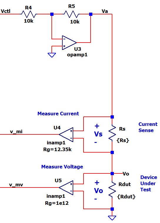
The system spec allows for Vs = +/-1V across current sense resistor Rs.
Rs = 1V / 0.010A = 100 ohms
Because the control loop's signals operate at +/-5V, we need to apply some gain
Kmi = V_mi / Vs = 5V / 1V = 5.0
(See Inst Amps below.)
The output voltage Vo is measured directly across the DUT. Important! The DUT drives the main purpose of the SMU! The user places a component (such as a resistor RDUT) to characterize its behavior and verify if it meets spec. The DUT can be a diode, capacitor, battery, etc.
INST AMPS
A standard instrumentation amp (like the AD620) senses the output voltage and current. You can set its gain with a single resistor
Kinst = Vout/ Vin = (1 + 49.4k/Rg)
Solving for the gain resistor Rg = 49.4k / (Kinst - 1)
To Measure Current across Rs we need to amplify Vs = +/-1V to V_mi = +/-5V
Rg = 49.4k / (5.0 - 1) = 12.35k
To Measure Voltage across Rdut we apply unity gain Vo = +/-5V to V_mv = +/-5V
Rg = 49.4k / (1 - 1) = ∞ (open)
FEEDBACK SELECT
A 2:1 Analog Mux (S1, S2) selects the feedback signal to the Error Amp: V_mv for Force Voltage mode, or V_mi for Force Current Mode.
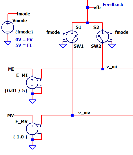
MEASURE VOLTAGE AND CURRENT
Lastly, E_MV and E_MI (simplified ADC + SW function) convert the control loop's voltage levels V_mv and V_mi into actual MV and MI. For example, a V_mi = 5V gets converted into an MI = 0.01A. (See SPICE section below).
EXCEL FILE
Explore the hands-on spreadsheet with the circuit calculations!
- Excel file:
SMU-FVFI-circuit-1.xlsx
Right Click on filename, select "Save link as...". - Play in the sandbox, modify values, predict the impact on circuit!
- Copy to a new file - experiment!
SPICE MODEL
Here's a high-level overview of the SMU's SPICE elements. Simpler models were chosen to focus on the SMU circuit topology, without getting lost in the SPICE details.
- V_SET creates a voltage (+/-5V) for the FV or FI set level
- Force Voltage: set = FV directly defines the desired Vo.
- Force Current: set = FI / 0.01A * 5V defines
the desired Io.
- Example for desired FI = 0.005A,
calculate set = 0.005A / 0.010A * 5V = 2.5V.
- Example for desired FI = 0.005A,
- Op Amps U1, U2 and U3 are modelled with open-loop gain in subcircuit OPAMP1.SUB.
- Inamps U4 and U5 are modelled with the gain set by passing the Rg value to subcircuit INAMP1.SUB.
- E_MV, E_MI model the ADC + Software that converts a voltage (+/-5V) to the
actual MV or MI reading.
- Measure Voltage: MV = V_mv directly reads the output voltage.
- Measure Current: MI = V_mi / 5V * 0.01A
scales the 5V measure signal to actual current.
- Example for measured V_mi = 2.5V,
calculate MI = 2.5V / 5V * 0.010A = 0.005 A.
- Example for measured V_mi = 2.5V,
- V_FMODE, S1 and S2 select the force mode
- FV: fmode = 0V, S1 = ON, S2 =OFF, vfb = V_mv
- FI: fmode = 5V, S1 = OFF, S2 =ON, vfb = V_mi
SIMULATION
Let's see the SMU circuit in action. For FV or FI mode, just enable / comment the relavant .PARAM statements:
- FV Mode, enable the SPICE directive:
.param fmode=0V FV=5V set=FV Rs=100 Rdut=20k
Comment out the FI params:
*.param fmode=5V ...
- FI Mode, enable the SPICE directive:
.param fmode=5V FI=0.01 set=FI/0.01A*5V Rs=100 Rdut=50
Comment out the FV params:
*.param fmode=0V ...
FV MODE Set the .PARAMs for FV mode and run a TRAN simulation of SMU-FVFI-ciruit-1.cir (or *.asc). Add traces -v(vset) and v(vfb). Does v(fb) rise to the set point v(vset)? Add another plot and trace v(mv) to view the Measure Voltage. Does v(mv) rise to the desired 5V?
FI MODE Set the .PARAMs for FI mode and run a TRAN simulation. Does v(fb) rise to the set point v(vset)? Add another plot and trace v(mi) to view the Measure Current - notice units in (V) but we know it represents (A). Does v(mi) rise to the desired 0.010A?
SPEED CONTROL Let's see how speed control works! Adjust Cint up by 2x or 3x and rerun the simulation. Does the output rise faster or slower?
SPICE NETLIST
Download SPICE Netlist or LTSPICE
Schematic
Right Click on filename, select "Save link as..."
* SMU-FVFI-circuit-1.asc
*
* Parameters
* FV Mode
.param fmode=0V FV=5V set=FV Rs=1k  Rdut=10k
* FI Mode
*.param fmode=5V FI=0.01 set=FI/0.01A*5V Rs=100 Rdut=50
*
* Set Point
V_SET vset 0 PWL(0us 0 1us {-set})
*
* Error Amp
R1 vset  N002  10k
R2 N002  vfb   10k
R3 error N002  10k
XU1 N002 0 error opamp1
*
* Controller (Integrator)
Rint N001  error 10k
Cint Vctl  N001  1nF
Rd1  Vctl  N001  10Meg
XU2 N001 0 Vctl opamp1
*
* Output Amp
R4  N003   Vctl  10k
R5  Va     N003  10k
XU3 N003 0 Va opamp1
*
* Current Sense
Rs  Va     Vo   {Rs}
*
* Device Under Test
Rdut Vo    0    {Rdut}
*
* INST AMP MI
XU4 Vo Va v_mi  inamp1 Rg=12.35k
*
* INST AMP MV
XU5 0 Vo v_mv  inamp1 Rg=1e12
*
* Measure Voltage and Current
E_MV  MV 0  v_mv 0  { 1.0 }
E_MI  MI 0  v_mi 0  {0.01 / 5}
*
* Force Mode
Vmode fmode 0 {fmode}
*
* Feedback Mux
S1  v_mv vfb   fmode 0   SW1
S2  v_mi vfb   fmode 0   SW2
*
* Simulation
.tran 200us
*
* Opamp Model ******************************
*  pin order      in- in+ out
.SUBCKT OPAMP1    1  2   3
EGAIN     3 0   2 1     1000K
.ENDS
*
* Inst Amp Model **************************
*  pin order      in- in+ out
.SUBCKT INAMP1    1  2   3
EGAIN     3 0    value={ (V(2)-V(1)) * (1+49.4k/Rg) }
.ENDS
*
* Switch Models **************************
.model SW1 SW(Ron=1 Roff=1Meg  Von=0V Voff=5V )
.model SW2 SW(Ron=1 Roff=1Meg  Von=5V Voff=0V )
*
.end
Back to SMU Series