Source Measure Unit
Crossover Circuit
Download SPICE
Netlist or LTSPICE
Schematic
Right Click on filename, select "Save link as..."
How does the SMU's control "cross over" from Force Mode to Clamp
Mode? The
answer is simple enough - pass the MINIMUM of the three errors (see
SMU with Clamps) to the next stage (the integrator).
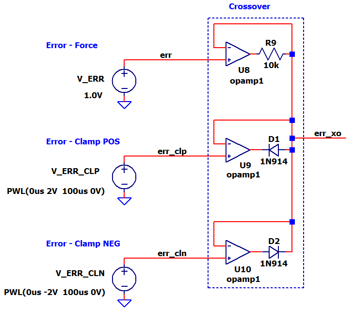
The Crossover is one of the most interesting circuits of the SMU - just three op amps and a few
key components.
Get a refresh of the SMU Circuit
Back to the SMU Series
CROSSOVER CIRCUIT
How does the Crossover pass the MINIMUM of the errors? Two cases reveal the how it's accomplished.
CASE 1: FORCE ERROR MINIMUM
- Force Error: err = +1V
- POS Clamp Error: err_clp = +2V
- NEG Clamp Error: err_cln = -2V
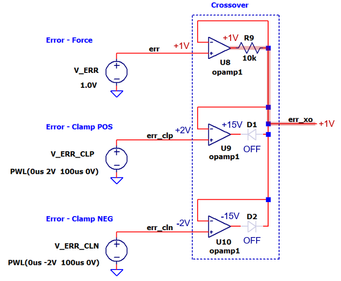
- U8 drives the Crossover output err_xo to +1V thru R9.
- U9 attempts to drive err_xo to +2V
- D1 reverse biases (turns OFF)
- U9's output goes to Pos Rail +15V
- U10 attempts to drive err_xo to -2V
- D2 reverse biases (turns OFF)
- U10's output goes to Neg Rail -15V
CASE 2: POS CLAMP ERROR MINIMUM
- Force Error: err = +1V
- POS Clamp Error: err_clp = +0.5V
- NEG Clamp Error: err_cln = -2V
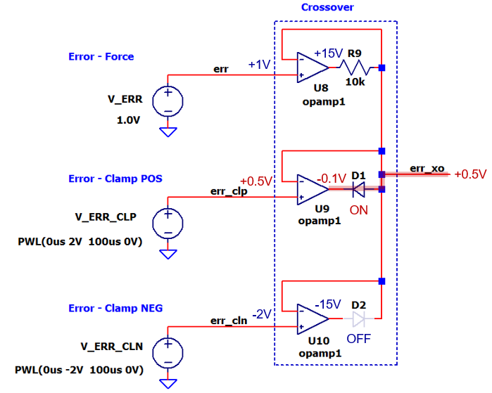
- U8 attempts to drive err_xo to +1V thru R9.
- Driving thru R9 = 10k cannot overtake control by U9 and D1.
- U8's output goes to Pos Rail +15V.
- U9 pulls down err_xo to -0.5V
- D1 forward biases (turns ON)
- U9's output goes to -0.1V pulling err_xo to +0.5V
- U10 attempts to drive err_xo to -2V
- D2 reverse biases (turns OFF)
- U10's output goes to Neg Rail -15V
The case of NEG CLAMP ERROR MINIMUM works similarly to the case above. Print out the schematic above, grab a pencil to mark up the voltages and observe how the NEG ERROR can take over control!
SIMULATION
How can you simulate a Crossover?
- Set the Force Error (err) to a DC Level of +1V.
- Set the POS Clamp Error to ramp down from +2V to 0V.
- Set the POS Clamp Error to ramp down from -2V to 0V.
Observe the crossover inputs / output and verify which error "wins" at driving the output.
POS CLAMP MODE Run a Transient Simulation of SMU-circuit-clamps-crossover-1.cir (or *.asc). Add traces for the Force Error v(err) and POS Clamp Error (err_clp) Add another Plot Window and Add trace for Crossover output v(err_xo).
Verify that initially the output follows v(err) = +1V. Where does the
output "cross over" to follow v(err_clp)? The POS Clamp Error should
overtake the output where V(err_clp) < v(err).
POS CLAMP MODE Change the Force Error voltage source VERR to -1V. Rerun the Transient Simulation and add a trace for NEG Clamp Error v(err_cln).
Verify that initially the output follows v(err) = -1V. Where does the output "cross over" to follow v(err_cln)? The NEG Clamp Error should overtake the output where V(err_cln) < v(err).
BONUS SIM Plot the op amp outputs! The "winner"
drives the output, while the others sit on a rail.
SPICE NETLIST
Download SPICE
Netlist or LTSPICE
Schematic
Right Click on filename, select "Save link as..."
* SMU Crossover Circuit
*
* Force Error
V_ERR err 0 1.0V
*
* Clamp POS Error
V_ERR_CLP err_clp 0 PWL(0us 2.0V 100us 0V)
*
* Clamp NEG Error
V_ERR_CLN err_cln 0 PWL(0us -2.0V 100us 0V)
*
* Crossover Circuit
* Force
XU8 err_xo err N001 opamp1
R9 err_xo N001 10k
*
* Clamp POS
XU9 err_xo err_clp N002 opamp1 Aol=1e6
D1 err_xo N002 1N914
*
* Clamp NEG
XU10 err_xo err_cln N003 opamp1
D2 N003 err_xo 1N914
*
* spice command
.tran 100us
*
* Op Amp Model
*  pin order    in- in+ out
.SUBCKT OPAMP1  1   2   4
*
GGAIN   0 3  2 1  1
RP1  3 0 1e6
EBUF  4 0  3 0  1.0
*
* V Limit
VP 10 0 +15V
VN 11 0 -15V
D1 3 10 1N914
D2 11 3 1N914
.ENDS
*
* diode model
.model 1N914 D(Is=2.52n Rs=.568 N=1.752 Cjo=4p M=.4 tt=20n)
*
.end
REFERENCES
- DIY Source Measure Unit, Dave Erickson, www.djerickson.com
- SMU Operation Modes Explained, Keysight Technologies, www.keysight.com
Back to SMU Series