Offset and Gain Error
Example Calculations
How can we apply Sensitivity Analysis to a basic circuit with errors? Let's walk through finding the Offset Error due to voff and the Gain Error due to R2 Tolerance. These are essential concepts for more complex error analysis! It took me a few trips around the rodeo to develop some understanding and skills. Take your time, refresh and repeat!
Back to EBA Series
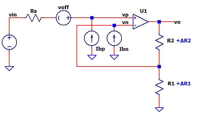
CIRCUIT BLOCK

OFFSET ERROR
Find Offset Sensitivity (S)
How does a change in voff cause a change in vo?
As you can see from the
schematic, it's the same as the non-inverting signal gain!
Evaluate S with Component Values
For R1 = 10k and R2 = 10k
Calculate Offset Error
For voff = 1mV, the offset error at vo is found as
GAIN ERROR
Find Gain Sensitivity (S)
How does a change in R2 cause a change in K?
The gain error is defined as a ratio.
where
K - ideal gain
K' - actual gain with errors
For the non-inverting amp, the Ideal Gain K and Actual Gain K’ can be written as
Learn more about calculating S using the Difference Method.
Evaluate S with Component Values
Calculate K and K' for R1 = 10k, R2 = 10k.
Choose an arbitrarily small
value of ΔR2, say 1% (0.01) for the S calculation.
Finally, we calculate S as ratio of gain error over resistor error.
What does S tell us?
For a 1% change in R2, the gain
will change by 0.5%.
SImilarly, for a 5% change in R2, the gain will change by
2.5%.
Calculate Gain Error
For an R2 Tolerance of 0.1%, the gain error is found as
TRY IT!
Jump into the hands-on spreadsheet!
- Excel File:
Offset_Gain_Sensitivity_and_Errors.xlsx
Right Click on the filename, select "Save link as...". - Play in the sandbox, modify values, see the impact on errors.
- Copy to a new file - experiment!
Signal Gain
- With R1=R2=10k, what is the circuit gain K?
Offset Error
- For voff (1mV), what is the Offset Sensitivity S and Error?
- Now change R1 or R2 to 2x or 1/2x the original value. What happens to S and ΔVoffset?
- Change voff=1mV to a different value, can you predict the error?
Gain Error
- Return values to R1=R2=10k.
- For R2 (1%), what is the Gain Sensitivity S and Error?
- Now change R1 or R2 to 2x or 1/2x the original value. What happens to S and ΔK/K?
- Change R1_Tol = 1% to a different value, can you predict the error?
CALCULATING SENSITIVITY
We chose an arbitrarily small value of ΔR2 to calc S. Why?
- Strictly speaking, S is defined as the Derivative Method (dK/K) / (dR/R) which can lead to some messy and difficult Calculus.
- Alternatively, the Difference Method (ΔK/K) / (ΔR/R) is easier and more efficlent to calculate using Algebra.
- For small values of ΔR, the Difference Method calculates the same S as the Derivative Method for all practical purposes.
- You should get a similar S for a ΔR of 0.01, 0.001, or 0.0001.
Check out the Difference vs. Derivative Methods.
NEXT UP
How do errors from a circuit block impact the larger Signal Chain?
Back to EBA Series