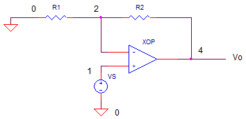
Op Amp Non-Inverting Amplifier
CIRCUIT

OPNON.CIR Download the SPICE file
VOLTAGE GAIN
Like the inverting amplifier, the opamp device simplifies the design of an amplifier stage. How? The gain of the stage depends on external resistors, not the internal gain of the op amp itself. The output voltage is determined by the input voltage and the ratio of the feedback resistors plus one.
![]()
Run a simulation on the circuit file “opnon.cir”.
Plot
the input V(1) and output V(4) of the Transient Analysis. With Vs=1Vp-p, R1 = 10k and R2
= 10k, does the output should produce a 2Vp-p signal of the same polarity?
HANDS-ON DESIGN You can change the gain by choosing a new value for R2. Double or triple R2 and calculate the new output voltage. (Example: Choose R2 = 30k and calculate Vo = 1 x (1+40k /10k = 4.) Edit the file with your new R2 value. Save the file and run a new simulation. Are the voltages at V(1) and V(4) what you expect?
NEGATIVE INPUT VOLTAGE
What is the voltage at the negative input of the op amp device? Run a simulation and plot the transient voltage at V(2). You should see that the negative input V(2) follows the input Vs. This is the prime directive of the op amp - do whatever it takes at vo to make input v- follow input v+ (which is also Vs).
How is this different compared to the inverting amplifier configuration? (See the Iverting Amplifier.)
BANDWIDTH
What is the bandwidth of this amplifier? Run a AC Analysis simulation with R1=10k, R2=20k and plot the output's magnitude V(4). The flat part of the magnitude VM(4) shows the frequencies within the bandwidth that the circuit is capable of amplifying. Above the bandwidth of the amplifier, the response begins to fall.
CIRCUIT ANALYSIS What happens to the bandwidth at higher gains. Increase the gain by increasing R2 to a value like 100k. What happens to the bandwidth at higher gain? Here's a classic compromise to be reckoned with: the trade-off between gain and bandwidth.
SIMULATION NOTE
The op amp is modeled using a subcircuit named OPAMP1. Although the guts of an op amp can contain 20 transistors or more, this model mimics only the higher level (or macro) functions of the device. The result is a simple model requiring only a handful of components. For a more detailed look inside, see the Basic Op Amp Model.
Subcircuits are handy ways of inserting a particular circuit into one or more places of the main circuit. They're easy to define and use. Check them out in Why Use Subcircuits?
SPICE FILE
Download the file or copy this netlist into a text file with the *.cir extention.
OPNON.CIR - OPAMP NON-INVERTING AMPLIFIER
*
VS	1	0	AC	1	SIN(0V	1VPEAK	10KHZ)
*
R1	2	0	10K
R2	2	4	10K
XOP	1 2	4	OPAMP1
*
* OPAMP MACRO MODEL, SINGLE-POLE
* connections:      non-inverting input
*                   |   inverting input
*                   |   |   output
*                   |   |   |
.SUBCKT OPAMP1      1   2   6
* INPUT IMPEDANCE
RIN	1	2	10MEG
* DC GAIN (100K) AND POLE 1 (100HZ)
EGAIN	3 0	1 2	100K
RP1	3	4	1K
CP1	4	0	1.5915UF
* OUTPUT BUFFER AND RESISTANCE
EBUFFER	5 0	4 0	1
ROUT	5	6	10
.ENDS
*
*.AC 	DEC 	5 1K 10MEG
.TRAN 	0.001MS  0.2MS
.PROBE
.END
© 2002 eCircuit Center