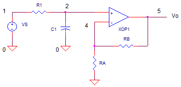
RC Low-Pass Filter
with Op Amp Buffer
CIRCUIT

OPFIL1.CIR Download the SPICE file
Many systems have unwanted signals that can corrupt your signal of interest: digital switching noise, 60 Hz AC power, switching power supply noise, motor drivers, clock oscillators, random noise from resistors and active devices, RF pickup, etc. For example, imagine you have a 5 kHz signal to be digitized. Unfortunately, a noise source at 50 kHz has coupled onto your signal. How can you stop the noise at high frequencies and pass the signal at low frequencies? A simple RC low-pass filter with an op amp buffer might do the trick.
But, why the op amp? It's the R and C in an RC filter that determine
the frequency response. The problem arises when you connect the filter
output to the next stage. The input resistance of the next stage will fall
directly across the C, changing the total R and the response of the filter.
To avoid this problem, you need to isolate the RC components from the next stage.
How? Enter the op amp. The
high input resistance of an op amp (typically > Gohms) has no significant
effect on the R of your filter.
LOW-PASS DESIGN
The key specification of a low-pass filter is the cuttoff frequency fc. Well below fc, the filter passes along without attenuation. Well above fc, the filter attenuates the signal. How much? As the frequency increases by a factor of 10x, the signal decreases by a factor of 10x. Let's design a filter to suppress (as best as this filter can) noise and pass our desired signal.
1. Choose a cutoff frequency fo (Hz).
As an example, select fo=10 kHz to reduce a noise signal at 50 kHz and pass your desired signals below 5 kHz.
2. Pick a convenient cap value C1 between 100pF and 0.1 uF.
Suppose you’ve got plenty of 1000pF caps in stock, select this value for C1.
4. Calculate R1 = 1 / (2 · π · fo · C1)
R1 = 1 / (2 · π · 10kHz · 1000pF) = 15.9 k ohms
OP AMP BUFFER
A buffer has two important qualities:
1) a high impedance input so that it won't effect the circuit it's buffering
2) a low impedance output to drive the required current into the next stage.
Need gain? Wire up the buffer as a standard non-inverting amplifier with gain RB/RA+1. If you don't need any gain, simply set the buffer as a unity gain follower (RB=short and RA=open).
CIRCUIT ANALYSIS Let's check out the frequency response of the filter we designed above. Run an AC Analysis and plot the output V(5). To get a better view, change the Y axis to a log scale. Where does the response fall from 1.0 to 0.707 (-3dB). How much does the gain decrease as the frequency increases by a factor of 10?
HANDS-ON DESIGN Pick a different cutoff frequency that's 10x or 1/10x the original. Change either the R or C by a factor of 10 to get the desired response. Rerun the simulation and check your output V(5).
HIGH-PASS FILTERS
HANDS-ON DESIGN Its easy to convert the low-pass filter to a high-pass filter. Just swap the resistor and capacitor locations – R1 with C1. Try out the high-pass circuit and plot the output V(5). Essentially, this response should be a mirror image of the low-pass flipped about the cutoff frequency.
TWO POLE FILTER
If you need more attenuation in the stop band, try a 2-pole Sallen-Key low-pass filter.
SPICE FILE
Download the file or copy this netlist into a text file with the *.cir extention.
OPFIL1.CIR - RC LOW-PASS FILTER WITH OPAMP BUFFER
*
VS	1	0	AC	1
*
R1	1	2	15.9K
C1	2	0	1000PF
*
* UNITY GAIN AMPLIFIER, RA=OPEN, RB=SHORT
RA	4	0	100MEG
RB	4	5	1k
XOP	2 4	5	OPAMP1
*
* OPAMP MACRO MODEL, SINGLE-POLE
* connections:      non-inverting input
*                   |   inverting input
*                   |   |   output
*                   |   |   |
.SUBCKT OPAMP1	     1   2   6
* INPUT IMPEDANCE
RIN	1	2	10MEG
* DC GAIN (100K) AND POLE 1 (100HZ)
* GBWP = 10MHz
EGAIN   3 0     1 2     100K
RP1     3       4       1K
CP1     4       0       1.5915UF
* OUTPUT BUFFER AND RESISTANCE
EBUFFER 5 0     4 0     1
ROUT    5       6       10
.ENDS
*
* ANALYSIS
.AC 	DEC 	10 100 1MEG
.PROBE
.END
© 2010 eCircuit Center