How Open-Loop Gain
Effects DC Accuracy
CIRCUIT

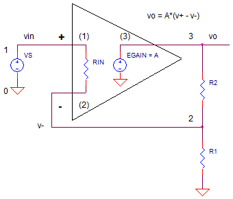
OP_AOL_DC1.CIR Download the SPICE file
Typically, the open-loop gain gets little attention from me on an op amp's data sheet. For most applications, I don't give a rip if it's A=100,000 (100 dB) or 1,000,000 (120 dB). It's seems big enough to make the gain defined by R1 and R2 a good approximation to the actual gain.
But, how does open loop gain (A) impact the success or failure of a high
precision design? A simple equation helps predict the error that can make or
break the performance of your system.
NON-INVERTING AMPLIFIER
For a non-inverting amplifier, what is the actual gain equation that
includes open loop gain, A?
Revisiting the circuit, for the op amp itself you can write the open-loop
gain equation as
vo = (v+ - v-)·A and for the resistors you can
write the feedback factor as B = v-/vo = R1/(R1+R2). Now combine these
along with v+=vin to get the closed-loop gain.
Kcl = vo / vin = A / (1+AB)
The power of feedback control systems occur when A*B >> 1, making the ideal closed loop gain
Kcl' = 1 / B = (R1+R2) / R1
The take away here is that the closed-loop signal gain Kcl is dependent mostly on R1 and R2, not the open loop gain A. This is good news because A can have huge variations and drift dramatically with temperature.
GAIN ERROR
However, for precision applications, A has some effect. How much?
From the gain equation above, you can rewrite it as
Kcl = 1/B · AB / (1+AB)
which looks like the ideal closed-loop gain
Kcl' = 1/B times an error term Err = AB / (1+AB)
When AB>>1, the Err is pretty darn close to 1. Just how close? That answer determines the accuracy of your circuit. To calculate the error, let's get a measure of how close the error term is to one.
Kcl_err = [ 1 - AB/(1+AB) ] / 1
For AB >> 1, you can simplify the gain error Kcl_err to
Kcl_err = 1/(A·B)
Now, you can calculate the error in percent or as an output voltage error.
GAIN ERROR IN PERCENT
Kcl_err = 1/(A B) · 100%
OUTPUT VOLTAGE ERROR
vo_err = vin · Kcl' · 1/(A B)
DESIGN EXAMPLE
As an example, a design calls for an amplifier a max input of Vin=1V
and a gain of 10x
(R2=9k, R1=1k)
feeding a 16-bit +/-10V ADC. The accuracy specification requires a gain error less than 1 LSB or 20V/2^16 = 305uV over +/25 C.
You're initial op amp choice has an A = 100,000. Unfortunately, over 25C, this gain changes by a factor of 2. So let's predict the initial voltage error at 25C
| Ideal Gain | Kcl' = 1/B = R1+R2/R1 = 10.000 | |
| Actual Gain | Kcl = A/(1+AB) = 9.999 | |
| Ideal Output | vo' = vin ·
Kcl' = vin · 1/B = vin · (R1+R2)/R1 = 10.000 |
|
| Actual Output | vo = vin · A/(1+AB) = 9.999V | |
| Output Error | vo_err = vo' - vo = 10.000V - 9.999V = 0.001V |
Is there an easier way to predict this error? Simply use the Kerr equation and the ideal gain Kcl'..
vo_err = vin · Kcl' · Kcl_err
= vin · Kcl' · 1/(AB)
= 1V · 10 · 10/100000
= 0.001V
The 1mV error has spilled over our error budget of 0.305uV. However, suppose in the best case, your system calibrates out this 1mV initial error at the factory. But we're still not out of the weeds yet - the spec needs to hold even a 25 deg temperature change!
GAIN DRIFT ERROR
The bugger here is that the op amp you've chosen has an open-loop gain A
that changes from 100k to 200k over 25C! What effect does that have on the
output error? Lets find the output error with A=200,000.
vo_err = vin · Kcl' · Kcl_err
= vin · (R1+R2)/R1 · 1/(AB)
= 1V · 10 · 10/200000
= 0.0005V
Bad news! The upshot is that even though we calibrated the 1mV error out when A=100k, the error changed by 0.5mV as the gain increased to 200k with a 25C temperature change. The bottom line is that the system will not hold the spec of 0.305mV!
So what can you do? The solution lies in choosing an op amp with a larger open-loop gain A. This reduces the initial error and, most likely, the change in error as A drifts with temperature.
SIMULATION
Let's simulate the non-inverting amp with
ideal resistor values R1 = 1000 and R2 = 9000 for a gain of +10.. With the
input signal at VS=1V, we expect to see an output voltage close to
V(3) = VS * (R1+R2)/R1 ≈ 10V.
Inside the simplified op amp model, the open-loop gain is set by the gain of EGAIN. Initially, set EGAIN to 100k. The ideal output at V(5) is generated a simple voltage controlled source EAMP1 set to an exact gain of 10.0
CIRCUIT INSIGHT Run a Transient Simulation and plot the output V(3). Place a cursor on the trace to get a precise reading of the output voltage. Is should be very close to, but not quite +10.0V. To see the ideal output, plot V(5). Finally, to find the output error, open a new window and plot V(3)-V(5). The error should be as calculated as above.
Now change EGAIN to 200k to simulate the change in open-loop gain over temperature. What is the new error? Is it what you expected?
HANDS-ON DESIGN How can we save this design? To lower the output error, you need to choose an op amp with a larger open-loop gain. Choose a new value for A that is 5x or 10x the original. Set EGAIN to this value. Rerun the simulation with your new value. Then double it to simulate a change in A versus a temperature change. Does the change in output fall below your design target of 0.305mV? If not, choose another op amp with an even higher open-loop gain.
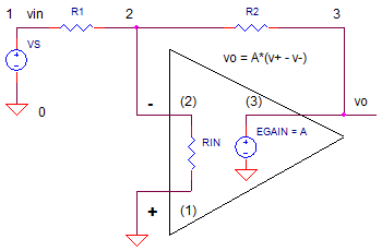
INVERTING AMPLIFIER
The gain equation for the inverting amplifier takes a little more
effort to calculate.

But it's very similar to the non-inverting amplifier.
Kcl = vo / vin = -R2/R1· AB /(1+AB)
Again, the power of feedback control systems occur when A*B >> 1, making the ideal closed loop gain
Kcl' = -R2 / R1
You can predict the output error as follows.
vo_err = vin · Kcl' · Kcl_err
= vin · -R2/R1 · 1/(AB)
Copy the SPICE file for the non-inverting amp to a new file. Then create a simulation for the inverting amplifier.
NEXT UP
What about the effect of open-loop gain
on the AC accuracy of your amplifier? The next topic builds on this topic to
see the accuracy of your circuit when passing a 20 kHz sine wave, for
example.
SPICE FILE
Download the file or copy this netlist into a text file with the *.cir extension.
OP_AOL_DC1.CIR
* INPUT
VS	1	0	ac	1	PWL(0US 0V   0.01US 1V)
*
* NON-INVERTING AMP
R1	2	0	1K
R2	3	2	9k
XOP1	1 2     3       op_001
*
* IDEAL NON-INVERTING GAIN
EAMP1	5 0 1 0		10
*
* BASIC OP AMP MODEL
*                 In+ In- Vout
.SUBCKT op_001    1   2   3
RIN   1   2   1e12
* OPEN LOOP GAIN
EGAIN   3 0 1 2	100000
*
.ENDS
*
* ANALYSIS *************************************
.TRAN 	1us  100us
.PROBE
.END
© 2011 eCircuit Center