Op Amp Control System - Part 2
CIRCUIT

OP_CONTROL.CIR
Download the
SPICE file
OP_CONTROL_OL.CIR
Download the
SPICE file
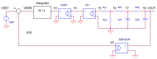
In Part 1, we explored a basic control system
based on the op amp and how it
works. But when your system begins to overshoot and oscillate, how do you
bring the behavior back under control?
Part 2 will analyze and design the system through the eyes of classic
control theory and open-loop analysis.
Using closed-loop transient analysis by itself can be like trying to plug a
leak in a sinking ship while working in partial darkness. However, you can
throw some light on the system by performing open-loop AC analysis to
illuminate the nature of the problem and possible solutions.
OP AMP CIRCUIT TO CONTROL
BLOCKS
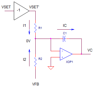
How do we transform the op amp controller into
it's classic control blocks of summing junction and controller (integrator)? Just write
out the circuit equations and noodle around until you got it in the proper
form.

Let's write some equations.
IC = I1 + I2
= VSET'/R1 + VFB/R2VC = -IC / (C1*s)
= -( VSET'/R1 + VFB/R2 ) / (C1*s)
NOTE: Recall from part 1, because the summing / integrator op amp is inverting, VSET must be set to the negative of our desired output. VSET' = VSET * -1. Sub this equation and make R1=R2.
Vo = ( VSET - VFB ) / (R1*C1*s)
= ( VSET - VFB ) * KI / s where KI = 1/(R1*C1)
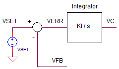
Okay - it looks like the classic equations for the summing junction and controller (integrator, in this case). Here are the classic control theory blocks for this op amp circuit.

The integrator block delivers big gain at low frequencies - good for accuracy of control system. However the gain rolls off at -20db/dec to unity gain at
fu_int = 1/(R1*C1)
OPEN-LOOP ANALYSIS
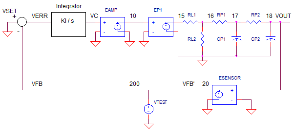
One way to perform open-loop analysis is to break open the loop, insert a test
signal VTEST and set VSET=0VRMS.
Where to make the break? One method breaks the circuit at a point where a
relatively low impedance is driving a relatively high impedance.
(Breaking the loop at this type of point preserves the behavior of the
stages even after the loop is broken.)

In this case, the feedback element (tachometer) is a good
point. Then insert an AC voltage source of 1 VRMS. And don't forget to set
VSET's AC
value to 0 VRMS.
Open-Loop Analysis is relatively simple:
1. Find response going around the loop by
plotting the Magnitude and Phase
of V(20)/V(200).
2. Check the Phase where the magnitude drops to unity (1V/V
or 0dB)
IF Phase ~ +90 deg (or -270 deg)
THEN Good response, no overshoot and ringing, may be a bit slow.
IF Phase ~ +45 deg (or -315 deg)
THEN Possible good response, some overshoot and ringing.
IF Phase ~ 0 deg (or -360 deg)
THEN You've got an oscillator, system out of control.
YOU CAN TUNE A LOOP
Let's start with a near ideal system: a fast response C1=0.1uF,
R1=R2=100k and no delay in the system (ideal motor) CP1=CP2=0.1pF. For each condition you can
follow a two step analysis:
1. Perform an open-loop analysis on OP_CONTROL_OL.CIR by running AC Analysis (frequency domain) using the .AC statement. Plot V(20)/V(200).
2. Perform a closed-loop analysis on OP_CONTROL.CIR by running a Transient Analysis (Time domain) using the .TRAN statement. Plot V(1) and V(20).
FAST RESPONSE - NO DELAY
Set integrator components R1=R2=100k, C1 = 0.1 uF and
the delay caps CP1=CP2=0.1pF. In the open-loop AC analysis plot, what
is the phase where the magnitude hits unity? It should be around +90 deg
(-279 deg). This is largely due to the integrator response (-90 deg) and
negative input of the summing junction (-180 deg) for a total of -270 or +90
deg phase shift. Now run a closed-loop response. It don't get much better
than this. A nice fast response with no overshoot or ringing!
ADD SOME DELAY
Set one of the delay caps to CP1=0.1uF. This mimics some of the
motor inertia or thermal mass of a heater. Looking at the open-loop AC
analysis plot, what starts happening to the phase where the magnitude hits
unity? Yup, the delay in the loop adds negative phase. cutting or
phase back to less than +90 deg. Now run a closed-loop response. The effects
of delay in the loop are clearly seen. Some overshoot emerges in the
response.
ADD MORE DELAY Set both caps to CP1=CP2-0.1uF. Things can only get worse. More delay in the loop means more phase shaft in the open-loop plot. Can you make a guess about the closed-loop response? This overshoot and ringing may be unacceptable at this point!
TUNE THE SYSTEM
A simple method to tuning is simply adjust the bandwidth
(via
C1) until you get the desired response. Let's try reducing the bandwidth
by making C1=0.1 uF larger by a factor of 2 or 4 or more. What happens to
the open-loop response? Reducing the bandwidth shifts the entire plot
DOWN. This means the response hits unity gain at a lower frequency where the phase is
more POSITIVE - a good thing! Run the closed-loop file. What happened
to the overshoot and ringing? It should be reduced - but at the cost of a
slower rise time.
OSCILLATIONS
Okay, let's see if we can make this system go wild. Let's try
increasing the bandwidth by making C1=0.1 uF smaller by a factor of 2 or 4
or more. What happens to the open-loop response? Reducing the bandwidth
should shift the entire plot UP. This means the unity gain occurs at a higher
frequency where the phase is more more NEGATIVE - a bad thing! Run the
closed-loop file. What happened to the response? You should see a
response out of control. If this were a real system - you may see smoke from
the power amp and real damage to the motor and gears.
NEXT UP
What happens when there's too much delay causing excessive overshoot
and ringing, but you're asked to design a fast response? You need to design a
lead-lag filter to create a system that responds quickly without the
overshoot.
OPEN-LOOP SPICE FILE
Download the file
or copy this netlist into a text file with the *.cir
extention.
OP_CONTROL_OL.CIR
*
* SET POINT
VS	100	0	AC 0
*
* INVERTER
EINV 1 0	100 0	-1
*
* OPEN-LOOP TEST VOLTAGE
VTEST	200	0	AC 1
*
* CLASSIC CONTROL AMPLIFIER
R1	1	2	100K
R2	200	2	100K
CI	2	3	0.1UF
XOP1	0 2     3       op_001
*
* POWER AMP WITH LIMIT
EAMP	10	0	VALUE = {  LIMIT( 1 * V(3), +15, -15 )  }
*
* PROCESS (MOTOR, HEATER, ETC)
EP1	15	0	VALUE = { 100 * V(10)  }
* LOSSES (FRICTION, HEAT LOSS, ETC.)
RL1	15	16	0.1
RL2	16	0	100
* DELAY (INERTIA, THERMAL MASS, ETC.)
RP1	16	17	100K
CP1	17	0	0.1PF
RP2	17	18	100K
CP2	18	0	0.1PF
*
* SENSOR (TACHOMETER, THERMISTOR, ETC.)
ESENSE	20	0	VALUE = { 1/100 * V(18)  }
*
*
 * BASIC OP AMP MODEL
* Device Pins     In+ In- Vout
.SUBCKT op_001    1   2   82
RIN   1   2   1e9
*   Aol=1000000, fu=1000000 Hz
G1   0    10  VALUE = { 1.0 * V(1,2)  }
R1   10   0   1e6
C1   10   0   1.59e-7
* OUTPUT STAGE
EOUT 80 0   10  0    1
ROUT 80     82    10
.ENDS
*
* ANALYSIS *************************************
*.TRAN 	0.1MS  1000MS
.AC DEC 20 0.01 1e5
.PROBE
.END
CLOSED-LOOP SPICE FILE
Download the file
or copy this netlist into a text file with the *.cir
extention.
OP_CONTROL.CIR
*
* SET POINT
VS	1	0	AC 1	PWL(0US 0V   0.01US -10V)
*
* CLASSIC CONTROL AMPLIFIER
R1	1	2	100K
R2	20	2	100K
CI	2	3	0.1UF
XOP1	0 2     3       op_001
*
* POWER AMP WITH LIMIT
EAMP	10	0	VALUE = {  LIMIT( 1 * V(3), +15, -15 )  }
*
* PROCESS (MOTOR, HEATER, ETC)
EP1	15	0	VALUE = { 100 * V(10)  }
* LOSSES (FRICTION, HEAT LOSS, ETC.)
RL1	15	16	0.1
RL2	16	0	100
* DELAY (INERTIA, THERMAL MASS, ETC.)
RP1	16	17	100K
CP1	17	0	0.1PF
RP2	17	18	100K
CP2	18	0	0.1PF
*
* SENSOR (TACHOMETER, THERMISTOR, ETC.)
ESENSE	20	0	VALUE = { 1/100 * V(18)  }
*
*
 * BASIC OP AMP MODEL
* Device Pins     In+ In- Vout
.SUBCKT op_001    1   2   82
RIN   1   2   1e9
*   Aol=1000000, fu=1000000 Hz
G1   0    10  VALUE = { 1.0 * V(1,2)  }
R1   10   0   1e6
C1   10   0   1.59e-7
* OUTPUT STAGE
EOUT 80 0   10  0    1
ROUT 80     82    10
.ENDS
*
* ANALYSIS *************************************
.TRAN 	0.1MS  1000MS
*.AC 	DEC 	20 0.1 1000MEG
.PROBE
.END
2010 eCircuit Center