Ultra-Lite Digital SMU
Part 3 - Testing Zeners, LEDs, Thermistors
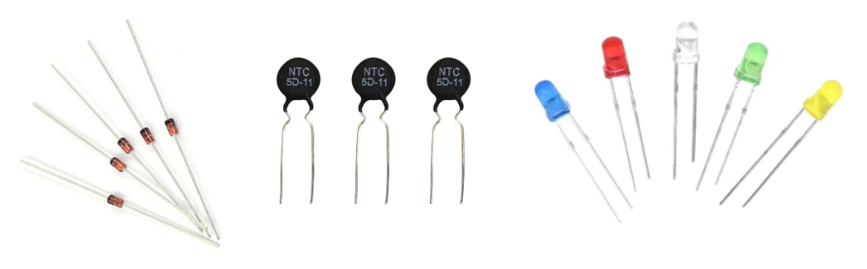
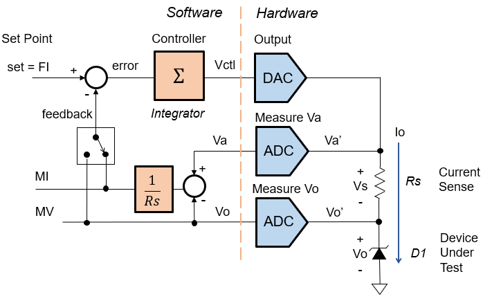
We've built an ultra-lite SMU to learn digital control and component
testing. Why? A small system provides an easy on-ramp to grasp bigger
ideas without getting lost in a myriad of circuit details. Later,
you can develop more complex SMU's on a solid foundation.
Part 1 - describes
/ simulates the essential
blocks of a digital SMU.
Part 2 - builds a prototype with an Arduino UNO and a few components.
Part 3 - tests real-world components.
Check out EXCEL test plan/calculator link below.
Back to SMU Series
ZENER - REVERSE VOLTAGE TEST
BZX79-B2V7, 2.7V, ±5%
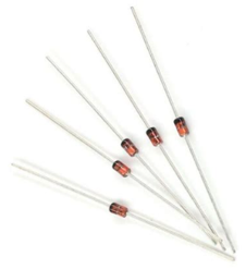
- Datasheet Specification:
Vz=+2.7V @ Iz=5mA - Test Strategy:
Force Current (FI), Measure Voltage (MV) - Edit test params in Arduino setup() code:
forceMode = FIMode;
FI = 0.005;
Rsense = 100;
Kint = 20000; - Install
Rs = 100
D1 = Cathode to Vo, Anode to GND - Test Limits
Vo = 2.6V to 2.8V - Expected Current Sense Voltage
Vs = Io*Rs = 0.005*100 = 0.5V - Check Voltage Headroom (must be greater than 0V)
Vhr = Vsupply - Vs - Vo
= 5V - 0.5V - 2.7V
= 1.8V (Pass!) - Expected Rise Time
(Rdut = Rz~100 ohms)
Tau = tr63% = 1/(Kint * Rs/(Rs+Rdut)*1/Rs)
= 1/ (20000 * 1/2 * 1/100)
= 10ms - Run the program
- Does the SMU servo the output current Io (MI) to ~5mA?
- What is the measured voltage? MV = 2.68V
- Check the test limits:
If 2.6V < Vo < 2.8V, then PASS , else FAIL.
ZENER - REVERSE LEAKAGE TEST
BZX79-B2V7, 20uA Max
- Datasheet Specification:
Iz<20uA @ Vz=1V - Test Strategy:
Force Voltage (FV), Measure Current (MI) - Edit test params in Arduino setup() code:
forceMode = FVMode;
FV = 1V;
Rsense = 100k;
Kint = 50; - Install
Rs = 100k
D1 = Cathode to Vo, Anode to GND - Test Limits
Iz < 20uA - Expected Current Sense Voltage
Vs = Io*Rs = 20uA*100k = 2V - Check Voltage Headroom (must be greater than 0V)
Vhr = Vsupply - Vs - Vo
= 5V - 2V - 1V
= 2V (Pass!) - Expected Time
Constant (Rdut = Rz~open)
Tau = tr63% = 1/(Kint * Rs/(Rs+Rdut))
= 1/ (20 * 1)
= 50ms - Run the program
- Does the SMU servo the output voltage Vo (MV) to ~1V?
- What is the measured current? MI = 3.7uA
- Check the test limits:
If Io < 20uA, then PASS , else FAIL.
THERMISTOR - RESISTANCE TEST
NTCLE100E3 103JBE (10k ±5% @ T=25C)
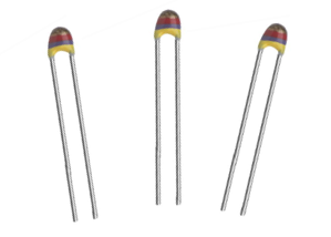
- Datasheet Specification:
Rth = 10kohms ±5% TCR=-4.38%/C @ T=25C - Test Strategy:
Force Voltage (FV), Measure Current (MI)
Calc Resistance (FV / MI) - Edit test params in Arduino setup() code:
forceMode = FVMode;
FV = 1V;
Rsense = 10k;
Kint = 50; - Install
Rs = 10k
Rth = ~10k - Expected Resistance at 21C (70 deg F)
Rth = R25 * ( 1 + (T - 25C)*TCR/100 )
= 10k * ( 1 + (21C - 25C)*-4.38%/100 )
= 10k * (1.1752)
= 11.75k - Test Limits
Rth = Rth +/-5% = 11.2k to 12.3k - Expected Current
Io = 1V/10k = 0.1mA - Expected Current Sense Voltage
Vs = Io*Rs = 0.1mA*10k = 1V - Check Voltage Headroom (must be greater than 0V)
Vhr = Vsupply - Vs - Vo
= 5V - 1V - 2V
= 2V (Pass!) - Expected Time
Constant (Rdut = Rth~10k)
Tau = tr63% = 1/(Kint * Rth/(Rs+Rdut))
= 1/ (50 * 0.5)
= 40ms - Run the program
- Does the SMU servo the output voltage Vo to 1V? MV = 1.01V
- What is the measured current? MI=0.086mA
- Calculate the Resistance: R = MV/MI = 11.7k
- Check the test limits:
If 11.2k < R < 12.3k, then PASS , else FAIL.
LED - FORWARD VOLTAGE TEST
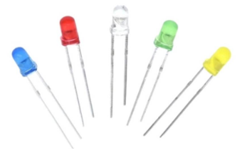
LTL-4224 Red LED, Vfwd=1.8V
- Datasheet Specification:
Vfwd=+1.8V ±0.3V @ Ifwd=5mA - Test Strategy:
Force Current (FI), Measure Voltage (MV) - Edit test params in Arduino setup() code:
forceMode = FIMode;
FI = 0.005;
Rsense = 100;
Kint = 2000; - Install
Rs = 100
D1 = Anode to Vo, Cathode to GND - Test Limits
Vo = 1.5V to 2.1V - Expected Current Sense Voltage
Vs = Io*Rs = 0.005*100 = 0.5V - Check Voltage Headroom (must be greater than 0V)
Vhr = Vsupply - Vs - Vo
= 5V - 0.5V - 1.8V
= 2.7V (Pass!) - Expected Rise Time (Rdut = Rfwd~1 ohms)
Tau = tr63% = 1/(Kint * Rs/(Rs+Rdut)*1/Rs)
= 1/ (2000 * 1 * 1/100)
= 50ms - Run the program
- Does the SMU servo the output current Io (MI) to ~5mA?
- What is the measured voltage? MV = 1.92V
- Check the test limits:
If 1.5V < Vo < 2.1V, then PASS , else FAIL.
EXCEL FILE
Explore the hands-on spreadsheet with the circuit calculations!
- Excel file:
SMU-FVFI-digital-lite-test-calc-1.xlsx
Right Click on filename, select "Save link as...". - Play in the sandbox, modify values, predict the impact on circuit!
- Copy to a new file - experiment!
Back to SMU Series