Precision Voltage String - Part 1
CIRCUIT
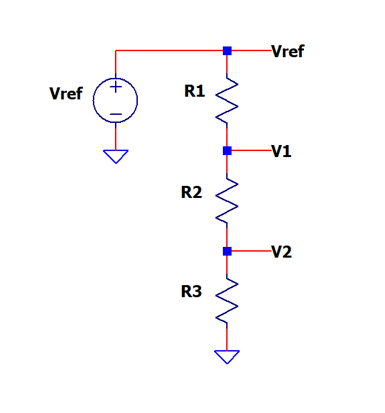
SPICE netlist: voltage-divider-string-1.cir
LTSPICE sch: voltage-divider-string-1.asc
Part 1 - intro to precision voltages using a resistor divider.
Part 2 - how accurate are these voltages?
Part 3 - two cool design methods using advanced Excel functions.
Specific voltage references are needed in many real-world applications - self diagnostics, internal calibration, comparator thresholds, level shifting, etc. One straight-forward method creates these levels through a resistor string and voltage reference.
How do you choose R1 - R3 for your desired voltages? How accurate are the voltages at V1 and V2? We'll create a SPICE file to not only verify the voltages, but discover the impact that a 1% resistor tolerance can have on each voltage level.
VOLTAGE DIVIDER BASICS
The voltage levels are easily calculated from the two equations.
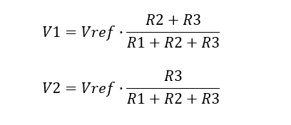
EXAMPLE
Suppose your circuit has the following components.
- Vref = 5V, R1 = 1k, R2 = 8k, R3 = 1k
Calculate the two voltage levels.
- V1 = 5V x 9k/10k = 4.5V
- V2 = 5V x 1k/10k = 0.5V
SPICE SIMULATION
Let's create a SPICE file using a DC source and resistors V_DIVIDER_STRING.CIR. We'll define the component values in a Parameter statement.
.param vref=5.0 R1=1k R2=8k R3=1k
Each component in the SPICE schematic defines its value using the curly brackets.
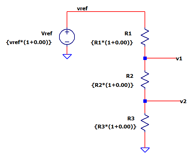
A handy way to add a resistor tolerance error is using the multiplier as follows.
{ R1*(1+0.00) }
The ideal value is as shown above. A 1% error is easily defined using the multiplier (1+0.01)
CIRCUIT INSIGHT Run a TRAN simulation with the Vref=5V, R1=1k, R2=8k R3 =1k and add trace V(V1). Does V1 reach its calculated level? Add another plot pane and trace V(V2). Does V(V2) acheive its expected value?
Now change R2 to something like 4k or 2k. Calculate the new voltages at V1 and V2. Verify your changes with a SPICE simulation.
CIRCUIT DESIGN
Given your specific voltage levels needed, how do you calculate the resistors? Applying some Intuition, here's a simple way
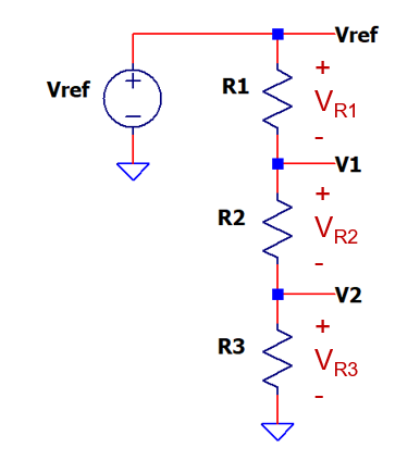
1. Choose your voltage levels V1 and V2.
2. Calculate how much voltage falls across each resistor

3. Calculate each resistor based on voltage ratio and
the total resistance (Rtot=R1+R2+R3).

EXAMPLE
You've been asked to create the test / calibration voltages
- V1 = 4V, V2 = 1V with Vref = 5V, Rtot = 10k
Calculate the voltage across each resistor.
- VR1 = Vref - V1 = 5.0 - 4.0 = 1V
- VR2 = V1 - V2 = 4.0 - 1.0 = 3V
- VR3 = V2 = 1V
Calculate each resistor.
- R1 = Rtot∙VR1/Vref = 10k∙ 1V/5V = 2k
- R2 = Rtot∙VR2/Vref = 10k∙ 3V/5V = 6k
- R3 = Rtot∙VR3/Vref = 10k∙ 1V/5V = 2k
IMPACT OF RESISTOR TOLERANCE
How does a 1% resistor tolerance impact the levels V1 and V2?
To measure the voltage errors, we'll create another string of ideal values, for comparison!
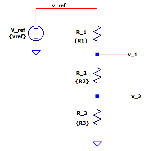
Notice how the underscore characters (example V_1) differentiates this string from the original.
ERROR IMPACT Run a TRAN simulation with the Vref=5V, R1=1k, R2=8k R3 =1k and open another Plot Pane.
To measure the error at V(V1) in %, let's add a formula
V(v1)-V(v_1))/V(v_1)*100
Let's do the same for V(V2) error in %.
V(v2)-V(v_2))/V(v_2)*100
Both errors should be 0!
Now, let's enter a 1% error for R2 and run a new simulation.
{ R2*(1+0.01) }
What are the voltage errors? For a +1% error in R2, you might expect a 1% error at both V1 and V2. Run a TRAN simulation and check out the errors.
- V1err = +0.09 %
- V2err = -0.80 %
Turns out both errors are less than 1% - though unexpected, this is good news! Restore R2 to ideal and try a 1% error for R1 or R3.
A Tolerance Analysis reveals the errors depend on resistor values and voltage. We'll dive into the Error Analysis in another topic coming soon.
SPICE FILE
Download the SPICE netlist file
voltage-divider-string-1.cir
or copy the netlist below into a text file with the *.cir extention.
* voltage-divider-string-1.cir
*
* Component values
.param vref=5.0 R1=1k R2=8k R3=1k
*
* Voltage String
Vref vref 0  {vref*(1+0.00)}
R1   vref v1 {R1*(1+0.00)}
R2   v1   v2 {R2*(1+0.00)}
R3   v2   0  {R3*(1+0.00)}
*
* Ideal Voltages, No Errors
V_ref v_ref 0   {vref}
R_1   v_ref v_1 {R1}
R_2   v_1   v_2 {R2}
R_3   v_2   0   {R3}
*
* Simulation
.tran 10us
.end
LTSPICE FILE
Download the LTSPICE schematic file voltage-divider-string-1.asc.
- Verify design, easily add resistor tolerance, calc errors.
EXCEL DESIGN CALCULATOR
Download the Excel design calculator file voltage-divider-string-design-calc-1.xlsx.
- Enter: Vref, V1, V2 and Rtotal
- Calc: R1,R2,R3
- Play in the sandbox, change values, predict what happens!
EXCEL ERROR ANALYSIS
Download the Error Budget Analysis calculator voltage-divider-string-errors-1.xlsx.
- Enter: Vref,R1,R2,R3
- Calc: Component Sensitivities, Voltage Errors
- Experiment, change values, predict what happens!