DAC Adjusts Supply Output
CIRCUIT
DAC-adjust-supply-vout-1.CIR Download the SPICE file
Why adjust your power supply output?
- Trim a rail to a precise level
- Compensate for the voltage drop to a load
- Test your circuit over a supply range (margining)
- Track rails to an ampifier's output for reduced device heat
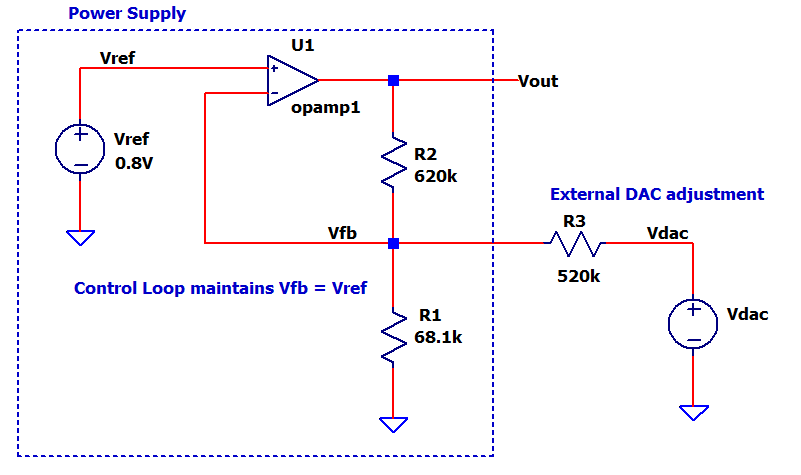
How can you adjust your fixed supply output with a DAC? The output is typically set by two resistors R1 and R2. However, adding R3 allows an external DAC voltage to adjust the supply output Vout. The method applies to many Linear Regulators as well as Switch-Mode Power Suppies (SMPS) such as Buck, Boost, etc.
I was surprised to find the analysis of a three resistor circuit to be quite challenging. But applying some classic EE methods takes you across the design finish line!
DAC ADJUST THEORY
Many classic power supply topologies look similar to schematic above (without R3) where Vout defined by a fixed output (b)
Vout = Vref ∙ (R2 + R1) / R1 = b
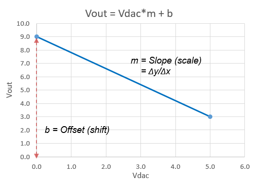
However, by adding R3 plus the DAC, you can Scale (m) and Shift (b) Vdac for a desired Vout.
Vout = Vdac∙m + b
where
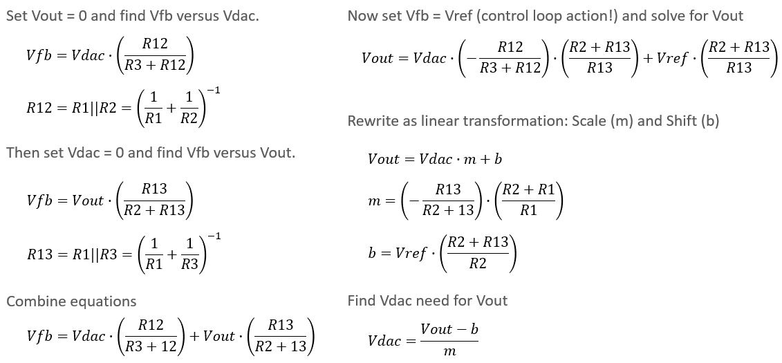
m = - R12 / (R3+R12) ∙ (R2+R13) / R13
b = Vref ∙ (R2+R13) / R13R12 = R1||R2 = 1/(1/R1 + 1/R2)
R13 = R1||R3 = 1/(1/R1 + 1/R3)Notice, with a negative m: an increasing Vdac creates a decreasing Vout.
Why are m and b important? So you can calculate the Vdac needed to achieve your desired output Vout!
Vdac = (Vout - b) / m
RESISTOR VALUES
Just 4 basic steps lead us to the circuit values. (See derivation of R's below.)
EXAMPLE: Set Vdac from 0 to 5V to adjust Vout from 9V to 3V (with Vref = 0.8V).
STEP 1
Select your desired Vdac and Vout input / output pairs that define the range of control.
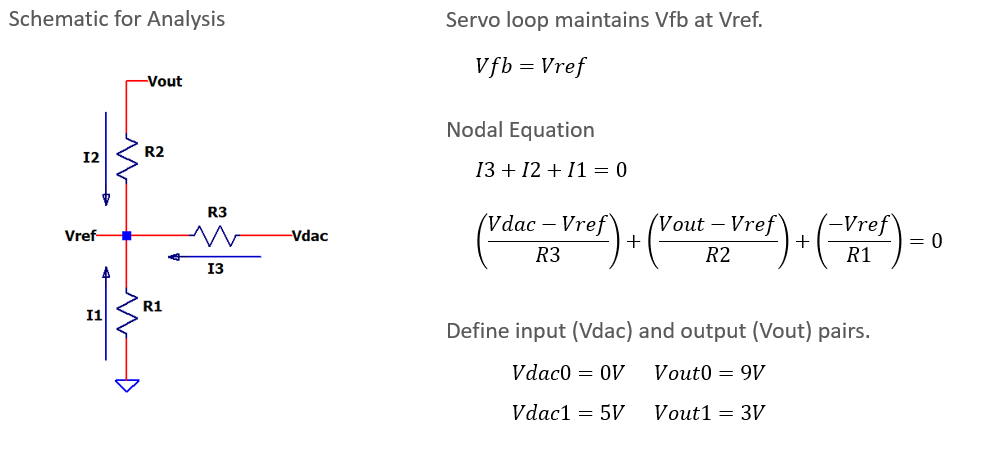
Vdac0 = 0V Vout0 = 9V
Vdac1 = 5V Vout1 = 3VCalculate IDEAL m = (Vout1 - Vout0) / (Vdac1 - Vdac0) = - 1.2
and b = Vout1 - m*Vdac1 = 9.0
STEP 2
Choose R3 = 100k and then calculate R2 and R1
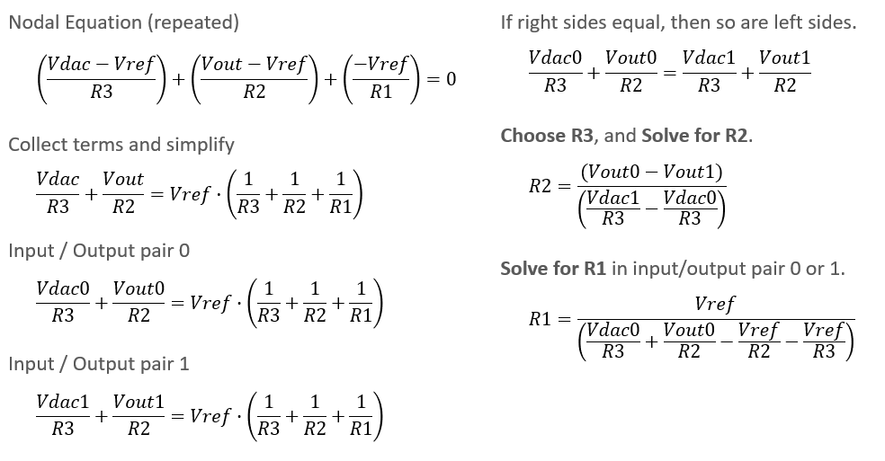
R2 = (Vout0 - Vout1 ) / (( Vdac1 - Vdac0)/R3 )
= 120 kCalculate R1.
R1 = Vref / ( Vout0/R2 + Vdac0/R3 - Vref/R2 - Vref / R3)
= 13.26 k
STEP 3
Scale all resistors (optional) and select standard or available values.
For example, suppose R1 = 68.1k is already on the PCB.Scale R2 and R3 by 68.1k / 13.26k.
Then select R2 = 620k and R3 = 510k
STEP 4
Calculate ACTUAL m and b (equations above) so you can set the required Vdac for the a desired Vout: Vdac = (Vout - b)/m.
m = -1.216
b = 9.056
EXCEL FILE
Explore the hands-on spreadsheet with all of the design calculations!
- Excel file: DAC-adjust-supply-vout-1.xlsx
Right Click on the filename, select "Save link as...". - Play in the sandbox, modify values, see the impact on circuit!
- Copy to a new file - experiment!
SPICE SIMULATION
It was exciting to see if all this derivation and calculation led to a useful circuit! Along the way we ran aground with several typos and mistakes which the resulted in negative resistance values - yikes! Eventually, the ship was righted and we arrived at
- R1 = 68.1k, R2 = 620k and R3 = 510k
These values promise to achieve Vout = 9V to 3V by driving Vdac = 0V to 5V.
The SPICE circuit models the entire supply with a simple op amp. Why? Both op amps and power supplies achieve one essential goal: move Vout so that Vfb is brought equal to Vref. A simple model let's us focus on the feedback R's and DAC, not the complexity of the supply itself.
We'll take advantage of SPICE's param command to verify our design.
.step param Vout 9V 3V -1V
.param m=-1.216 b=9.056
.param Vdac = (Vout - b) / m
The step param allows multiple simulation runs while
stepping through the desired Vout from 9V to 3V in increments of -1V. The
next params set the variables m and b so
that we can calculate the Vdac needed to achieve the
desired actual Vout.
CIRCUIT INSIGHT Run a TRAN simulation of DAC-adjusts-PS1.cir. In the plot window add trace v(vdac). Add a Plot Pane and then add a trace for the output v(Vout). We're looking to verify multiple SPICE runs to show Vout = 9V, 8V, 7V, 6V, 5V, 4V and 3V.
To read the voltages on the trace, Right-Click on v(Vout) and then hit the UP or DN Arrow to move cursor between multiple runs. How close did v(Vout) hit the targets?
Right-Click on v(Vdac) to see what voltages were needed for Vout. Did the Vdac span from approximately 0V to 5V as expected?
SPICE FILE
Download the file or copy this netlist into a text file with the *.cir extention.
* DAC-adjust-supply-vout-1.cir
*
* Sim parameters
.step  param Vout 9V 3V -1V
.param m=-1.216 b=9.056
.param Vdac = (Vout-b)/m
*
* Feedback R's
R1  0     Vfb  68.1k
R2  Vout  Vfb  620k
R3  Vdac  Vfb  510k
*
* DAC voltage
Vdac Vdac 0 {Vdac}
*
* Vref and Power Supply (Op Amp)
Vref Vref     0    0.8V
XU1  Vfb Vref Vout opamp1
*
* Op Amp Model ************************
* pin order      in- in+ out
.SUBCKT OPAMP1   1   2   3
EGAIN  3 0  2 1  1000K
.ENDS
****************************************
*
* Run transient response
.tran 20us
*
* VIEW RESULTS
.PROBE
.END
LTSPICE SCHEMATIC
![]() Explore the simulation, hit the run icon amd view traces!
Explore the simulation, hit the run icon amd view traces!
- LTSPICE file: DAC-adjust-supply-vout-1.asc
Right Click on the filename, select "Save link as...". - Play in the sandbox, modify values, see the impact on circuit!
- Copy to a new file - experiment!
CIRCUIT ANALYSIS
The analysis for even a simple resisitor circuit can be challenging! But just start noodling around with classic EE methods (nodal analysis and superposition) to arrive at some useful calculations. (Download the PDF of theory / analysis here.)
TRANSFER FUNCTION
First up, let's find the function that describes Vout versus Vdac that looks like Vout = Vdac*m+b. We'll apply the Supersposition Theorem to find voltage at Vfb and then derive m and b.
CALCULATE R1, R2, R3
Here we apply Nodal Analysis to circuit below along with the input / output voltage pairs that define the range of control.
With some further deriving and noodling, we solve for the resistor values! (Looks all neat here after some trial and error with paper and pencil.)
HANDS-ON PROJECT WITH ARDUINO
Prototype this application using an Arduino and a Buck-Boost SMPS Module from Sparkfun. Program the Arduino's DAC (PWM output pin) through an added resistor to digitally control the DCDC Converter's Vout. Customize for your own needs with an handy Excel file (link above).
https://www.instructables.com/Use-a-DAC-to-Adjust-a-Supplys-Vout-With-an-Arduino/