Source Measure Unit (SMU)
Force Current
How It Works
Download SPICE Netlist or LTSPICE Schematic
Right Click on filename, select "Save link as..."
Similar to Force Voltage mode, let's create a Source Measure Unit (SMU)
to Force Current mode using basic system blocks. Why?
Learning these simple blocks helps you develop basic understanding and intuition.
Later you can build more complex SMUs on this foundational understanding.
With a hands-on SPICE model, you can source current and measure voltage
(FIMV) to verify a resistance spec.
Back to SMU Series
FORCE CURRENT
This mode Forces a Current across the Device-Under-Test (DUT) and Measures the Voltage. Why is this useful?
Consider a low-value Resistor Test Specification: R = 50.0 ± 5% at 1mA. Notice how the test spec calls out a condition, in this case 1mA. So the SMU's test mission is to
- Force the Condition (FI = 1mA)
- Measure the Parameter (MV = Vo)
- CCalc R = MV/FI and Check if passes within Limits (50.0 ± 5%)
BASIC BLOCKS
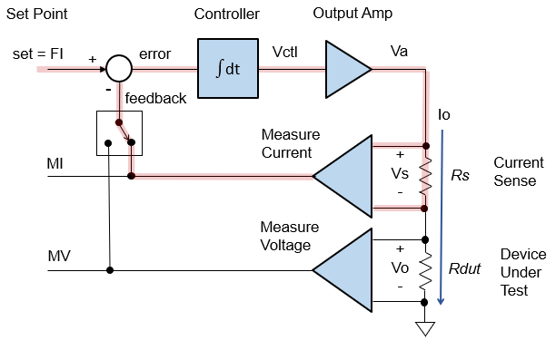
How can you implement the Force Current mode? SMUs typically implement the classic current feedback loop.
- Set Point FI - where do you want Io to go?
- Feedback MI - where is Io now?
- Error - what's the difference between set FI and feedback MI,
- Controller - given the error = FI - MI, how do we adjust Vctl to get there?
- Amplifier - provides drive (voltage / current) to the Device Under Test (DUT).
- Measure Current - senses output current through Rs (MI).
- Measure Voltage - senses output voltage (MV).
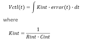
INTEGRAL CONTROL
The Controller is implemented with an integrator - a simple, yet powerful function. What's its role? The Integrator keeps a continuous running total of the error over time. Note, in the integration equation below, the ∫ represents the letter S for a Summation.
To see how it works intuitively, let's choose set = 1mA.
- Initially with Io = 0mA, a portion of the error = set - feedback = 1mA - 0mA = 1mA gets summed over time (integrated) so that Vctl begins to rise quickly.
- As Io gets close to target, say Io = 0.9mA, a smaller error = 1.0mA - 0.9mA = 0.1mA gets summed and Vctl rises more slowly.
- Finally, with Io = 1.0mA, a zero error = 1.0mA - 1.0mA = 0mA gets summed and Vctl HOLDS STEADY - goal reached!
You can choose Kint (the portion of error to be summed) to control the
speed of the control loop.
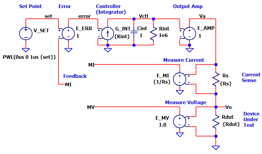
SPICE CIRCUIT - HOW IT WORKS
- V_SET creates a voltage for the FI set level.
(Note, V_SET is a voltage, but we know it represents a current level.)- PWL( 0us 0 1us {set} ) defines the time / value pairs of a step input.
- Most of the system blocks are modelled with a basic voltage in/out
device.
- E_ERR - Error Amplifier (K = 1)
- E_AMP - Output Amplifier (K = 1)
- E_MI - Measure Current (K = 1/Rs)
1/Rs converts voltage across Rs back into current level.
- E_MV - Measure Voltage (K = 1)
- The integrator is modelled by G_INT (converts the error into a current)
and Cint (integrates current).
- Kint scales how much of error gets integrated
- useful for speed (bandwidth) control
- Select Force Mode (connect either MV or MI as feedback).
- For Force Current: set netname at E_ERR (-) input to MI.
- For Force Voltage: set netname at E_ERR (-) input to MV.
- .TRAN 100ms requests a Transient (time) simluation for 0 to 100ms.
SIMULATION
Let's take this SMU out for a test drive. Just two actions are needed:
- Set the netname on the feedback net (E_ERR, neg input) to MI.
- Enable the parameters for FI:
.param set=0.001 Rs=100 Rdut=50 Kint=10000
Comment out the FV params:
*.param set=10.0 Rs=100 Rdut=20k Kint=100
CIRCUIT INSIGHT Run a TRAN simulation of SMU-FVFI-basic-0.cir (or *.asc). Add traces v(set) and v(mi). Does MI rise to the set point of 1.0mA? Add v(error) and observe - does v(error) get smaller as v(mi) approaches v(set).
RESISTANCE MEASURE Let's perform a resistance test. First, measure the DUT current by opening another plot window and adding trace v(mv). Finally, to calculate resistance, add another plot window and trace v(mv)/v(mi). Does your test verify Rdut = 50 ohms?
SPEED CONTROL Now try your hand at speed control! Adjust Kint up or down by 2x and rerun the simulation. Does v(mi) rise faster or slower?
SPICE NETLIST
Download SPICE Netlist or LTSPICE
Schematic
Right Click on filename, select "Save link as..."
* SMU-FVFI-basic-1.asc
*
* Set Params
* FV
*.param set=10.0 Rs=100 Rdut=20k Kint=100
* FI
.param set=0.001 Rs=100 Rdut=50 Kint=20000
*
* Set Point
VSET  set  0  PWL(0us 0 1us {set})
*
* Error
* FV Mode: set E_ERR (-) input to MV
* FI Mode: set E_ERR (-) input to MI
E_ERR error 0  set MI  1.0
*
* Controller (Integrator)
G_INT  0 Vctl  error 0  {Kint}
Cint  Vctl  0  1
Rint  Vctl  0  1e6
*
* Output Amp
E_AMP  Va 0  Vctl 0  1.0
*
* Current Sense
Rs  Va  Vo  {Rs}
*
* Device Under Test
Rdut  Vo  0  {Rdut}
*
* Measure Current
E_MI  MI 0  Va Vo  {1/Rs}
*
* Measure Voltage
E_MV  MV 0  Vo 0  1.0
*
* SIMULATION
.tran 100ms
.probe
.end
Back to SMU Series